
Car Amplifier User Manual


Table Of Contents
- Safety Instructions
- COMPLIANCE WITH EC DIRECTIVES
- CONFORMANCE WITH UL/C-UL STANDARD
- <
> - CONTENTS
- Optional Servo Motor Instruction Manual CONTENTS
- 1. FUNCTIONS AND CONFIGURATION
- 2. INSTALLATION
- 3. SIGNALS AND WIRING
- 3.1 Standard connection example
- 3.2 Internal connection diagram of servo amplifier
- 3.3 I/O signals
- 3.4 Detailed description of the signals
- 3.5 Alarm occurrence timing chart
- 3.6 Interfaces
- 3.7 Input power supply circuit
- 3.8 Connection of servo amplifier and servo motor
- 3.9 Servo motor with electromagnetic brake
- 3.10 Grounding
- 3.11 Servo amplifier terminal block (TE2) wiring method
- 3.12 Instructions for the 3M connector
- 3.13 Power line circuit of the MR-J2S-11KA to MR-J2S-22KA
- 4. OPERATION
- 5. PARAMETERS
- 6. DISPLAY AND OPERATION
- 7. GENERAL GAIN ADJUSTMENT
- 8. SPECIAL ADJUSTMENT FUNCTIONS
- 9. INSPECTION
- 10. TROUBLESHOOTING
- 11. OUTLINE DIMENSION DRAWINGS
- 12. CHARACTERISTICS
- 13. OPTIONS AND AUXILIARY EQUIPMENT
- 13.1 Options
- 13.1.1 Regenerative brake options
- 13.1.2 Brake unit
- 13.1.3 Power regeneration converter
- 13.1.4 External dynamic brake
- 13.1.5 Cables and connectors
- 13.1.6 Junction terminal block (MR-TB20)
- 13.1.7 Maintenance junction card (MR-J2CN3TM)
- 13.1.8 Battery (MR-BAT, A6BAT)
- 13.1.9 MR Configurator (Servo configurations software)
- 13.1.10 Power regeneration common converter
- 13.1.11 Heat sink outside mounting attachment (MR-JACN)
- 13.2 Auxiliary equipment
- 13.2.1 Recommended wires
- 13.2.2 No-fuse breakers, fuses, magnetic contactors
- 13.2.3 Power factor improving reactors
- 13.2.4 Power factor improving DC reactors
- 13.2.5 Relays
- 13.2.6 Surge absorbers
- 13.2.7 Noise reduction techniques
- 13.2.8 Leakage current breaker
- 13.2.9 EMC filter
- 13.2.10 Setting potentiometers for analog inputs
- 13.1 Options
- 14. COMMUNICATION FUNCTIONS
- 14.1 Configuration
- 14.2 Communication specifications
- 14.3 Protocol
- 14.4 Character codes
- 14.5 Error codes
- 14.6 Checksum
- 14.7 Time-out operation
- 14.8 Retry operation
- 14.9 Initialization
- 14.10 Communication procedure example
- 14.11 Command and data No. list
- 14.12 Detailed explanations of commands
- 14.12.1 Data processing
- 14.12.2 Status display
- 14.12.3 Parameter
- 14.12.4 External I/O pin statuses (DIO diagnosis)
- 14.12.5 Disable/enable of external I/O signals (DIO)
- 14.12.6 External input signal ON/OFF (test operation)
- 14.12.7 Test operation mode
- 14.12.8 Output signal pin ON/OFF output signal (DO) forced output
- 14.12.9 Alarm history
- 14.12.10 Current alarm
- 14.12.11 Other commands
- 15. ABSOLUTE POSITION DETECTION SYSTEM
- 15.1 Outline
- 15.2 Specifications
- 15.3 Battery installation procedure
- 15.4 Standard connection diagram
- 15.5 Signal explanation
- 15.6 Startup procedure
- 15.7 Absolute position data transfer protocol
- 15.8 Examples of use
- 15.9 Confirmation of absolute position detection data
- 15.10 Absolute position data transfer errors
- Appendix
- REVISIONS
10 - 9
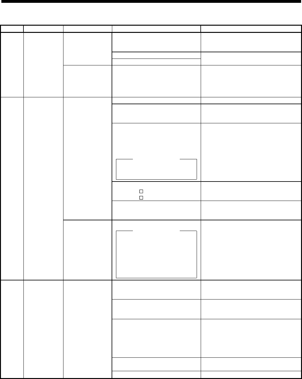
10. TROUBLESHOOTING
Display Name Definition Cause Action
1. Reduced voltage of super capacitor
in encoder
After leaving the alarm occurring for a few
minutes, switch power off, then on again.
Always make home position setting again.
2. Battery voltage low
Absolute position
data in error
3. Battery cable or battery is faulty.
Change battery.
Always make home position setting again.
AL.25 Absolute
position erase
Power was switched
on for the first time
in the absolute
position detection
system.
4. Super capacitor of the absolute
position encoder is not charged
After leaving the alarm occurring for a few
minutes, switch power off, then on again.
Always make home position setting again.
1. Wrong setting of parameter No. 0 Set correctly.
2. Built-in regenerative brake
resistor or regenerative brake
option is not connected.
Connect correctly
3. High-duty operation or continuous
regenerative operation caused the
permissible regenerative power of
the regenerative brake option to
be exceeded.
Checking method
Call the status display and check
the regenerative load ratio.
1. Reduce the frequency of positioning.
2. Use the regenerative brake option of
larger capacity.
3. Reduce the load.
4. Power supply voltage is abnormal.
MR-J2S-
A:260VAC or more
MR-J2S-
A1:135VAC or more
Review power supply
Permissible
regenerative power
of the built-in
regenerative brake
resistor or
regenerative brake
option is exceeded.
5. Built-in regenerative brake
resistor or regenerative brake
option faulty.
Change servo amplifier or regenerative
brake option.
AL.30 Regenerative
alarm
Regenerative
transistor fault
6. Regenerative transistor faulty.
Checking method
1) The regenerative brake option
has overheated abnormally.
2) The alarm occurs even after
removal of the built-in
regenerative brake resistor or
regenerative brake option.
Change the servo amplifier.
1. Input command pulse frequency
exceeded the permissible
instantaneous speed frequency.
Set command pulses correctly.
2. Small acceleration/deceleration
time constant caused overshoot to
be large.
Increase acceleration/deceleration time
constant.
3. Servo system is instable to cause
overshoot.
1. Re-set servo gain to proper value.
2. If servo gain cannot be set to proper
value:
1) Reduce load inertia moment ratio; or
2) Reexamine acceleration/
deceleration time constant.
4. Electronic gear ratio is large
(parameters No. 3, 4)
Set correctly.
AL.31 Overspeed Speed has exceeded
the instantaneous
permissible speed.
5. Encoder faulty. Change the servo motor.