
Car Amplifier User Manual


Table Of Contents
- Safety Instructions
- COMPLIANCE WITH EC DIRECTIVES
- CONFORMANCE WITH UL/C-UL STANDARD
- <
> - CONTENTS
- Optional Servo Motor Instruction Manual CONTENTS
- 1. FUNCTIONS AND CONFIGURATION
- 2. INSTALLATION
- 3. SIGNALS AND WIRING
- 3.1 Standard connection example
- 3.2 Internal connection diagram of servo amplifier
- 3.3 I/O signals
- 3.4 Detailed description of the signals
- 3.5 Alarm occurrence timing chart
- 3.6 Interfaces
- 3.7 Input power supply circuit
- 3.8 Connection of servo amplifier and servo motor
- 3.9 Servo motor with electromagnetic brake
- 3.10 Grounding
- 3.11 Servo amplifier terminal block (TE2) wiring method
- 3.12 Instructions for the 3M connector
- 3.13 Power line circuit of the MR-J2S-11KA to MR-J2S-22KA
- 4. OPERATION
- 5. PARAMETERS
- 6. DISPLAY AND OPERATION
- 7. GENERAL GAIN ADJUSTMENT
- 8. SPECIAL ADJUSTMENT FUNCTIONS
- 9. INSPECTION
- 10. TROUBLESHOOTING
- 11. OUTLINE DIMENSION DRAWINGS
- 12. CHARACTERISTICS
- 13. OPTIONS AND AUXILIARY EQUIPMENT
- 13.1 Options
- 13.1.1 Regenerative brake options
- 13.1.2 Brake unit
- 13.1.3 Power regeneration converter
- 13.1.4 External dynamic brake
- 13.1.5 Cables and connectors
- 13.1.6 Junction terminal block (MR-TB20)
- 13.1.7 Maintenance junction card (MR-J2CN3TM)
- 13.1.8 Battery (MR-BAT, A6BAT)
- 13.1.9 MR Configurator (Servo configurations software)
- 13.1.10 Power regeneration common converter
- 13.1.11 Heat sink outside mounting attachment (MR-JACN)
- 13.2 Auxiliary equipment
- 13.2.1 Recommended wires
- 13.2.2 No-fuse breakers, fuses, magnetic contactors
- 13.2.3 Power factor improving reactors
- 13.2.4 Power factor improving DC reactors
- 13.2.5 Relays
- 13.2.6 Surge absorbers
- 13.2.7 Noise reduction techniques
- 13.2.8 Leakage current breaker
- 13.2.9 EMC filter
- 13.2.10 Setting potentiometers for analog inputs
- 13.1 Options
- 14. COMMUNICATION FUNCTIONS
- 14.1 Configuration
- 14.2 Communication specifications
- 14.3 Protocol
- 14.4 Character codes
- 14.5 Error codes
- 14.6 Checksum
- 14.7 Time-out operation
- 14.8 Retry operation
- 14.9 Initialization
- 14.10 Communication procedure example
- 14.11 Command and data No. list
- 14.12 Detailed explanations of commands
- 14.12.1 Data processing
- 14.12.2 Status display
- 14.12.3 Parameter
- 14.12.4 External I/O pin statuses (DIO diagnosis)
- 14.12.5 Disable/enable of external I/O signals (DIO)
- 14.12.6 External input signal ON/OFF (test operation)
- 14.12.7 Test operation mode
- 14.12.8 Output signal pin ON/OFF output signal (DO) forced output
- 14.12.9 Alarm history
- 14.12.10 Current alarm
- 14.12.11 Other commands
- 15. ABSOLUTE POSITION DETECTION SYSTEM
- 15.1 Outline
- 15.2 Specifications
- 15.3 Battery installation procedure
- 15.4 Standard connection diagram
- 15.5 Signal explanation
- 15.6 Startup procedure
- 15.7 Absolute position data transfer protocol
- 15.8 Examples of use
- 15.9 Confirmation of absolute position detection data
- 15.10 Absolute position data transfer errors
- Appendix
- REVISIONS
5 - 26
5. PARAMETERS
5.2 Detailed description
5.2.1 Electronic gear
CAUTION
Wrong setting can lead to unexpected fast rotation, causing injury.
POINT
The guideline of the electronic gear setting range is
50
1
CDV
CMX
500.
If the set value is outside this range, noise may be generated during
acceleration/ deceleration or operation may not be performed at the preset
speed and/or acceleration/deceleration time constants.
The following specification symbols are required to calculate the electronic
gear.
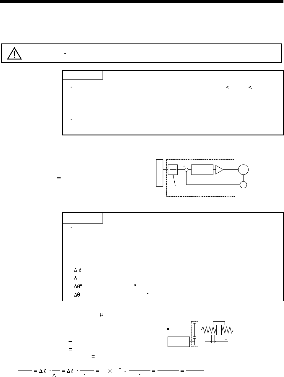
(1) Concept of electronic gear
The machine can be moved at any multiplication factor to input pulses.
CDV
CMX
Parameter No.4
Parameter No.3
Electronic gear
Feedback pulse
CMX
CDV
Deviation
counter
Motor
Encoder
Input pulse train
The following setting examples are used to explain how to calculate the electronic gear:
POINT
The following specification symbols are required to calculate the electronic
gear
Pb : Ballscrew lead [mm]
n : Reduction ratio
Pt : Servo motor resolution [pulses/rev]
0
:
Travel per command pulse [mm/pulse]
S
:
Travel per servo motor revolution [mm/rev]
:
Angle per pulse [
/pulse]
: Angle per revolution [ /rev]
(a) For motion in increments of 10 m per pulse
Machine specifications
Ballscrew lead Pb
10 [mm]
Reduction ratio: n
1/2
Servo motor resolution: Pt
131072 [pulses/rev]
Servo motor
131072 [pulse/rev]
n
NM
NL
Pb 10[mm]
n NL/NM
1/2
CDV
CMX
0
Pt
S
0
Pt
n Pb
10
10
3
1/2 10
131072
262144
1000
32768
125
Hence, set 32768 to CMX and 125 to CDV.