General-Purpose AC Servo J2-Super Series SSCNET Compatible J2-Super Series MODEL MR-J2S- B SERVO AMPLIFIER INSTRUCTION MANUAL MR-J2S- B Servo Amplifier Instruction Manual MODEL CODE G MODEL MR-J2S-B GIJUTU SIRYOU 1CW502 HEAD OFFICE : TOKYO BLDG MARUNOUCHI TOKYO 100-8310 SH (NA) 030007-G (0711) MEE Printed in Japan This Instruction Manual uses recycled paper. Specifications subject to change without notice.
Safety Instructions (Always read these instructions before using the equipment.) Do not attempt to install, operate, maintain or inspect the servo amplifier and servo motor until you have read through this Instruction Manual, Installation guide, Servo motor Instruction Manual and appended documents carefully and can use the equipment correctly. Do not use the servo amplifier and servo motor until you have a full knowledge of the equipment, safety information and instructions.
1. To prevent electric shock, note the following: WARNING Before wiring or inspection, turn off the power and wait for 15 minutes or more until the charge lamp turns off. Then, confirm that the voltage between P and N is safe with a voltage tester and others. Otherwise, an electric shock may occur. In addition, always confirm from the front of the servo amplifier, whether the charge lamp is off or not. Connect the servo amplifier and servo motor to ground.
. Additional instructions The following instructions should also be fully noted. Incorrect handling may cause a fault, injury, electric shock, etc. (1) Transportation and installation CAUTION Transport the products correctly according to their weights. Stacking in excess of the specified number of products is not allowed. Do not carry the servo motor by the cables, shaft or encoder. Do not hold the front cover to transport the servo amplifier. The servo amplifier may drop.
CAUTION Securely attach the servo motor to the machine. If attach insecurely, the servo motor may come off during operation. The servo motor with reduction gear must be installed in the specified direction to prevent oil leakage. Take safety measures, e.g. provide covers, to prevent accidental access to the rotating parts of the servo motor during operation. Never hit the servo motor or shaft, especially when coupling the servo motor to the machine. The encoder may become faulty.
(3) Test run adjustment CAUTION Before operation, check the parameter settings. Improper settings may cause some machines to perform unexpected operation. The parameter settings must not be changed excessively. Operation will be insatiable. (4) Usage CAUTION Provide a forced stop circuit to ensure that operation can be stopped and power switched off immediately. Any person who is involved in disassembly and repair should be fully competent to do the work.
(6) Maintenance, inspection and parts replacement CAUTION With age, the electrolytic capacitor of the servo amplifier will deteriorate. To prevent a secondary accident due to a fault, it is recommended to replace the electrolytic capacitor every 10 years when used in general environment. Please consult our sales representative. (7) General instruction To illustrate details, the equipment in the diagrams of this Instruction Manual may have been drawn without covers and safety guards.
COMPLIANCE WITH EC DIRECTIVES 1. WHAT ARE EC DIRECTIVES? The EC directives were issued to standardize the regulations of the EU countries and ensure smooth distribution of safety-guaranteed products.
(4) Power supply (a) Operate the servo amplifier 7kW or less to meet the requirements of the overvoltage category II set forth in IEC60664-1. For this purpose, a reinforced insulating transformer conforming to the IEC or EN standard should be used in the power input section. Since the 11kW or more servo amplifier can be used under the conditions of the overvoltage category III set forth in IEC60664-1, a reinforced insulating transformer is not required in the power input section.
CONFORMANCE WITH UL/C-UL STANDARD (1) Servo amplifiers and servo motors used Use the servo amplifiers and servo motors which comply with the standard model. Servo amplifier Servo motor :MR-J2S-10B to MR-J2S-22KB MR-J2S-10B1 to MR-J2S-40B1 :HC-KFS HC-MFS HC-SFS HC-RFS HC-UFS HA-LFS HC-LFS (2) Installation Install a cooling fan of 100CFM (2.8m3/min) air flow 4 in (10.16 cm) above the servo amplifier or provide cooling of at least equivalent capability.
<> This Instruction Manual and the MELSERVO Servo Motor Instruction Manual are required if you use the General-Purpose AC servo MR-J2S-B for the first time. Always purchase them and use the MRJ2S-B safely. Also read the manual of the servo system controller. Relevant manuals Manual name Manual No.
CONTENTS 1. FUNCTIONS AND CONFIGURATION 1- 1 to 1-22 1.1 Introduction.............................................................................................................................................. 1- 1 1.2 Function block diagram .......................................................................................................................... 1- 2 1.3 Servo amplifier standard specifications .............................................................................................
3.12 Power line circuit of the MR-J2S-11KB to MR-J2S-22KB ............................................................... 3-32 3.12.1 Connection example ...................................................................................................................... 3-33 3.12.2 Servo amplifier terminals ............................................................................................................. 3-34 3.12.3 Servo motor terminals...........................................................
8. INSPECTION 8- 1 to 8- 2 9. TROUBLESHOOTING 9- 1 to 9- 8 9.1 Alarms and warning list ......................................................................................................................... 9- 1 9.2 Remedies for alarms................................................................................................................................ 9- 2 9.3 Remedies for warnings................................................................................................................
13.2 Specifications ....................................................................................................................................... 13- 2 13.3 Battery installation procedure ........................................................................................................... 13- 3 13.4 Confirmation of absolute position detection data............................................................................. 13- 4 APPENDIX App- 2 App 1.
Optional Servo Motor Instruction Manual CONTENTS The rough table of contents of the optional MELSERVO Servo Motor Instruction Manual is introduced here for your reference. Note that the contents of the Servo Motor Instruction Manual are not included in the Servo Amplifier Instruction Manual. 1. INTRODUCTION 2. INSTALLATION 3. CONNECTORS USED FOR SERVO MOTOR WIRING 4. INSPECTION 5. SPECIFICATIONS 6. CHARACTERISTICS 7. OUTLINE DIMENSION DRAWINGS 8.
MEMO 6
1. FUNCTIONS AND CONFIGURATION 1. FUNCTIONS AND CONFIGURATION 1.1 Introduction The Mitsubishi MELSERVO-J2-Super series general-purpose AC servo is based on the MELSERVO-J2 series and has further higher performance and higher functions. It is connected with a servo system controller or similar device via a serial bus (SSCNET) and the servo amplifier reads position data directly to perform operation.
1. FUNCTIONS AND CONFIGURATION 1.2 Function block diagram The function block diagram of this servo is shown below.
1.
1.
1. FUNCTIONS AND CONFIGURATION 1.
1. FUNCTIONS AND CONFIGURATION 1.4 Function list The following table lists the functions of this servo. For details of the functions, refer to the reference field. Function Description Reference High-resolution encoder High-resolution encoder of 131072 pulses/rev is used as a servo motor encoder. Absolute position detection system Merely setting a home position once makes home position return unnecessary Chapter 13 at every power-on.
1. FUNCTIONS AND CONFIGURATION 1.5 Model code definition (1) Rating plate MITSUBISHI MODEL MR-J2S-60B AC SERVO AC SERVO Model Capacity POWER : 600W POWER INPUT : 3.2A 3PH 1PH200-230V 50Hz 3PH 1PH200-230V 60Hz 5.5A 1PH 230V 50/60Hz OUTPUT : 170V 0-360Hz 3.
1. FUNCTIONS AND CONFIGURATION 1.6 Combination with servo motor The following table lists combinations of servo amplifiers and servo motors. The same combinations apply to the models with electromagnetic brakes and the models with reduction gears.
1. FUNCTIONS AND CONFIGURATION 1.7 Structure 1.7.1 Parts identification (1) MR-J2S-100B or less Name/Application Reference Battery holder Section 13.3 Contains the battery for absolute position data backup. Battery connector (CON1) Used to connect the battery for absolute position data Section 13.3 backup. Display The two-digit, seven-segment LED shows the servo status and alarm number. Chapter 4 Axis select switch (SW1) SW1 EF B CD 345 78 9 Used to set the axis number of the servo amplifier.
1. FUNCTIONS AND CONFIGURATION (2) MR-J2S-200B MR-J2S-350B POINT The servo amplifier is shown without the front cover. For removal of the front cover, refer to section 1.7.2. Name/Application Reference Battery holder Contains the battery for absolute position data backup. Section 13.3 Battery connector (CON1) Used to connect the battery for absolute position data Section 13.3 backup. Display The two-digit, seven-segment LED shows the servo status and alarm number.
1. FUNCTIONS AND CONFIGURATION (3) MR-J2S-500B POINT The servo amplifier is shown without the front cover. For removal of the front cover, refer to section 1.7.2. Section 13.3 Battery holder Contains the battery for absolute position data backup. Section 13.3 Chapter 4 BCD 45 A EF 23 Reference Display The two-digit, seven-segment LED shows the servo status and alarm number. 89 67 Name/Application Battery connector (CON1) Used to connect the battery for absolute position data backup.
1. FUNCTIONS AND CONFIGURATION (4) MR-J2S-700B POINT The servo amplifier is shown without the front cover. For removal of the front cover, refer to section 1.7.2. Name/Application Reference Battery connector (CON1) Used to connect the battery for absolute position data backup. Section 13.3 Battery holder Contains the battery for absolute position data backup. Section 13.3 Chapter 4 EF 23 BCD 45 89 A 67 Display The two-digit, seven-segment LED shows the servo status and alarm number.
1. FUNCTIONS AND CONFIGURATION (5) MR-J2S-11KB or more POINT The servo amplifier is shown without the front cover. For removal of the front cover, refer to section 1.7.2. Name/Application Reference Axis select switch (SW1) 0 EF 1 2 345 BCD SW1 Used to set the axis number of the servo amplifier. Section 3.11 8 67 9A Display The two-digit, seven-segment LED shows the servo status and alarm number. Battery holder Contains the battery for absolute position data backup. Chapter 4 Section 13.
1. FUNCTIONS AND CONFIGURATION 1.7.2 Removal and reinstallation of the front cover Before removing or installing the front cover, turn off the power and wait for 15 minutes or more until the charge lamp turns off. Then, confirm that the voltage between P and N is safe with a voltage tester and others. Otherwise, an electric shock may occur. In addition, always confirm from the front of the servo amplifier whether the charge lamp is off or not.
1. FUNCTIONS AND CONFIGURATION (3) For MR-J2S-700B Reinstallation of the front cover Removal of the front cover Front cover hook (2 places) A) B) 2) 2) 1) A) 1) Front cover socket (2 places) 1) Push the removing knob A) or B), and put you finger into the front hole of the front cover. 2) Pull the front cover toward you. 1) Insert the two front cover hooks at the bottom into the sockets of the servo amplifier. 2) Press the front cover against the servo amplifier until the removing knob clicks.
1. FUNCTIONS AND CONFIGURATION Reinstallation of the front cover Mounting screws (2 places) 2) Fix it with the mounting screws (2 places). 1) Insert the front cover in the direction of arrow. Mounting screws (2 places) 3) Fit the front cover and fix it with the mounting screws (2 places).
1. FUNCTIONS AND CONFIGURATION 1.8 Servo system with auxiliary equipment WARNING To prevent an electric shock, always connect the protective earth (PE) terminal ( of the servo amplifier to the protective earth (PE) of the control box. ) (1) MR-J2S-100B or less (a) For 3-phase 200V to 230V or 1-phase 230V Options and auxiliary equipment (Note 2) Power supply Reference Reference No-fuse breaker Section 12.2.2 Regenerative option Section 12.1.1 Magnetic contactor Section 12.2.
1. FUNCTIONS AND CONFIGURATION (b) For 1-phase 100V to 120V (Note 2) Power supply Options and auxiliary equipment Reference Reference No-fuse breaker Section 12.2.2 Regenerative option Section 12.1.1 Magnetic contactor Section 12.2.2 Cables Section 12.2.1 MR Configurator Section 12.1.
1. FUNCTIONS AND CONFIGURATION (2) MR-J2S-200B MR-J2S-350B (Note) Power supply No-fuse breaker (NFB) or fuse Options and auxiliary equipment Options and auxiliary equipment Reference No-fuse breaker Section 12.2.2 Regenerative option Section 12.1.1 Magnetic contactor Section 12.2.2 Cables Section 12.2.1 MR Configurator (Servo configuration software) Section 12.1.8 Power factor improving reactor Section 12.2.
1. FUNCTIONS AND CONFIGURATION (3) MR-J2S-500B (Note 2) Power supply Options and auxiliary equipment No-fuse breaker (NFB) or fuse Reference Section 12.2.2 Regenerative option Section 12.1.1 Magnetic contactor Section 12.2.2 Cables Section 12.2.1 MR Configurator (Servo configuration software) Section 12.1.8 P (Note 1) C Regenerative option To CN1A To CN1B U V W Power factor improving reactor Section 12.2.
1. FUNCTIONS AND CONFIGURATION (4) MR-J2S-700B Options and auxiliary equipment (Note 2) Power supply Reference Reference No-fuse breaker Section 12.2.2 Regenerative option Section 12.1.1 Magnetic contactor Section 12.2.2 Cables Section 12.2.1 MR Configurator (Servo configuration software) Section 12.1.8 Power factor improving reactor Section 12.2.
1. FUNCTIONS AND CONFIGURATION (5) MR-J2S-11KB or more Options and auxiliary equipment (Note 3) Power supply Reference Options and auxiliary equipment No-fuse breaker Section 12.2.2 Regenerative option Section 12.1.1 Magnetic contactor Section 12.2.2 Cables Section 12.2.1 MR Configurator (Servo configuration software) Section 12.1.8 Power factor improving reactor Section 12.2.3 Power factor improving DC reactor No-fuse breaker(NFB) or fuse Section 12.2.
2. INSTALLATION 2. INSTALLATION Stacking in excess of the limited number of products is not allowed. Install the equipment on incombustible material. Installing them directly or close to combustibles will lead to a fire. Install the equipment in a load-bearing place in accordance with this Instruction Manual. Do not get on or put heavy load on the equipment to prevent injury. Use the equipment within the specified environmental condition range. (For the environmental conditions, refer to section 1.3.
2. INSTALLATION 2.2 Installation direction and clearances CAUTION The equipment must be installed in the specified direction. Otherwise, a fault may occur. Leave specified clearances between the servo amplifier and control box inside walls or other equipment. (1) Installation of one servo amplifier Control box Control box 40mm (1.6 in.) or more Servo amplifier Wiring clearance 70mm (2.8 in.) Top 10mm (0.4 in.) or more 10mm (0.4 in.) or more Bottom 40mm (1.6 in.
2. INSTALLATION (2) Installation of two or more servo amplifiers Leave a large clearance between the top of the servo amplifier and the internal surface of the control box, and install a cooling fan to prevent the internal temperature of the control box from exceeding the environmental conditions. Control box 100mm (4.0 in.) or more 10mm (0.4 in.) or more Servo amplifier 30mm (1.2 in.) or more 30mm (1.2 in.) or more 40mm (1.6 in.
2. INSTALLATION 2.4 Cable stress (1) The way of clamping the cable must be fully examined so that flexing stress and cable's own weight stress are not applied to the cable connection. (2) For use in any application where the servo motor moves, fix the cables (encoder, power supply, brake) supplied with the servo motor, and flex the optional encoder cable or the power supply and brake wiring cables. Use the optional encoder cable within the flexing life range.
3. SIGNALS AND WIRING 3. SIGNALS AND WIRING Any person who is involved in wiring should be fully competent to do the work. WARNING Before wiring, turn off the power and wait for 15 minutes or more until the charge lamp turns off. Then, confirm that the voltage between P and N is safe with a voltage tester and others. Otherwise, an electric shock may occur. In addition, always confirm from the front of the servo amplifier whether the charge lamp is off or not.
3. SIGNALS AND WIRING 3.1 Connection example of control signal system POINT Refer to section 3.5 for the connection of the power supply system and to section 3.6 for connection with the servo motor. 3.1.1 MR-J2S-700B or less Servo amplifier (Note 5, 8) 10m(32.81ft) or less CN3 RA1 13 MBR (Note 9) MR Configurator (Servo configuration software) (Note 4) Personal computer CN3 15m(49.
3. SIGNALS AND WIRING Note 1. To prevent an electric shock, always connect the protective earth (PE) terminal ( ) of the servo amplifier to the protective earth (PE) of the control box. 2. Connect the diode in the correct direction. If it is connected reversely, the servo amplifier will be faulty and will not output signals, disabling the forced stop (EM1) and other protective circuits. 3. If the controller does not have a forced stop function, always install a forced stop switch (Normally closed). 4.
3. SIGNALS AND WIRING 3.1.2 MR-J2S-11KB or more Servo amplifier (Note 4) CN3 6 (Note 7) Personal computer MR Configurator (Servo configuration software) 15m(49.2ft) or less CN3 Servo system controller (Note 8, 12) Bus cable (Option) (Note 4) CN1A LA 16 LAR 7 LB 17 LBR 8 LZ 18 LZR 1 LG Plate SD Encoder A-phase pulse (differential line driver) Encoder B-phase pulse (differential line driver) Encoder Z-phase pulse (differential line driver) 10m(32.
3. SIGNALS AND WIRING Note 1. To prevent an electric shock, always connect the protective earth (PE) terminal ( ) of the base unit to the protective earth (PE) of the control box. 2. Connect the diode in the correct direction. If it is connected reversely, the interface unit will be faulty and will not output signals, disabling the forced stop and other protective circuits. 3. If the controller does not have a forced stop (EM1) function, always install a forced stop switch (Normally closed). 4.
3. SIGNALS AND WIRING 3.2 I/O signals 3.2.1 Connectors and signal arrangements POINT The pin configurations of the connectors are as viewed from the cable connector wiring section.
3. SIGNALS AND WIRING (2) MR-J2S-11KB or more CN3 1 CN4 2 1 MO1 2 MO2 4 RXD LG 3 4 11 12 TXD 6 LA 8 LZ 13 14 5 LG LG 15 16 7 LB 9 10 LAR 18 LZR 17 LBR 19 20 MITSUBISHI CN1A Same as the one of the MR-J2S-700B or less. CON2 CN1B Same as the one of the MR-J2S-700B or less.
3. SIGNALS AND WIRING 3.2.2 Signal explanations For the I/O interfaces (symbols in I/O column in the table), refer to section 3.4.2. (1) Connector applications Connector CN1A CN1B Name Connector for bus cable from preceding axis.
3. SIGNALS AND WIRING 3.3 Alarm occurrence timing chart When an alarm has occurred, remove its cause, make sure that the operation signal is not being input, ensure safety, and reset the alarm before restarting operation. CAUTION As soon as an alarm occurs, make the Servo off status and interrupt the main circuit power. When an alarm occurs in the servo amplifier, the base circuit is shut off and the servo motor is coated to a stop. Switch off the main circuit power supply in the external sequence.
3. SIGNALS AND WIRING 3.4 Interfaces 3.4.1 Common line The following diagram shows the power supply and its common line. To conform to the EMC directive, refer to the EMC Installation Guide lines (IB(NA)67310). Servo amplifier 24VDC VDD COM MBR RA EM1 DI-1 SG LA .etc Differential line driver output 35mA max. LAR .
3. SIGNALS AND WIRING 3.4.2 Detailed description of the interfaces This section gives the details of the I/O signal interfaces (refer to I/O Division in the table) indicated in section 3.2.2. Refer to this section and connect the interfaces with the external equipment. (1) Digital input interface DI-1 Give a signal with a relay or open collector transistor. Servo amplifier VDD COM 24VDC R: Approx. 4.7 For a transistor EM1 Approx. 5mA Switch SG TR V CES 1.
3. SIGNALS AND WIRING (b) Lamp load Servo amplifier 24VDC VDD COM R MBR SG (3) Encoder pulse output DO-2 (Differential line driver system) 1) Interface Max. output current: 35mA Servo amplifier Servo amplifier LA (LB, LZ) Am26LS32 or equivalent LA (LB, LZ) 100 High-speed photocoupler 150 LAR (LBR, LZR) LAR (LBR, LZR) LG SD SD 2) Pulse output Servo motor CCW rotation LA LAR Time cycle (T) is determined by the settings of parameter No.33 and 38.
3. SIGNALS AND WIRING (4) Analog output Output voltage : 10V Max.
3. SIGNALS AND WIRING 3.5 Power line circuit CAUTION Always connect a magnetic contactor (MC) between the main circuit power supply and L1, L2, and L3 of the servo amplifier, and configure the wiring to be able to shut down the power supply on the side of the servo amplifier’s power supply. If a magnetic contactor (MC) is not connected, continuous flow of a large current may cause a fire when the servo amplifier malfunctions. Switch power off at detection of an alarm.
3. SIGNALS AND WIRING (2) For 1-phase 100 to 120V or 1-phase 230V power supply (Note 1) Alarm RA1 Controller forced stop RA2 Forced stop OFF ON MC MC SK Power supply 1-phase 100 to 120V or 1-phase 230V NFB MC L1 Servo amplifier L2 L3 (Note 2) L11 L21 VDD COM Forced stop EM1 SG Note 1. Configure up the power supply circuit which switches off the magnetic contactor after detection of alarm occurrence on the controller side. 2. Not provided for 1-phase 100 to 120V.
3. SIGNALS AND WIRING 3.5.2 Terminals The positions and signal arrangements of the terminal blocks change with the capacity of the servo amplifier. Refer to section 10.1. Symbol Connection Target (Application) Description Supply L1, L2 and L3 with the following power. For 1-phase 230V, connect the power supply to L1/L2 and leave L3 open.
3. SIGNALS AND WIRING 3.5.3 Power-on sequence (1) Power-on procedure 1) Always wire the power supply as shown in above section 3.5.1 using the magnetic contactor with the main circuit power supply (3-phase 200V: L1, L2, L3, 1-phase 230V: L1, L2, 1-phase: L1 L2). Configure up an external sequence to switch off the magnetic contactor as soon as an alarm occurs.
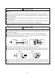
3. SIGNALS AND WIRING 3.6 Connection of servo amplifier and servo motor 3.6.1 Connection instructions WARNING CAUTION Insulate the connections of the power supply terminals to prevent an electric shock. Connect the wires to the correct phase terminals (U, V, W) of the servo amplifier and servo motor. Otherwise, the servo motor will operate improperly. Do not connect AC power supply directly to the servo motor. Otherwise, a fault may occur.
3. SIGNALS AND WIRING Servo motor Connection diagram Servo motor Servo amplifier U (Red) U V W V (White) W (Black) Motor (Green) (Note 1) 24VDC B1 HC-KFS053 (B) to 73 (B) HC-MFS053 (B) to 73 (B) HC-UFS13 (B) to 73 (B) B2 EM1 To be shut off when servo-off or alarm occurrence (Note 2) Electromagnetic brake CN2 Encoder Encoder cable Note 1. To prevent an electric shock, always connect the protective earth (PE) terminal ( servo amplifier to the protective earth (PE) of the control box. 2.
3. SIGNALS AND WIRING 3.6.3 I/O terminals (1) HC-KFS HC-MFS HC-UFS3000r/min series Encoder connector signal arrangement Power supply lead 4-AWG19 0.3m (0.98ft.) a Encoder cable 0.3m (0.98ft.
3. SIGNALS AND WIRING (2) HC-SFS HC-RFS HC-UFS2000 r/min series Servo motor side connectors Servo motor HC-SFS81(B) HC-SFS121(B) to 301(B) HC-SFS202(B) to 502 (B) 353(B) HC-RFS103(B) to 203 (B) Encoder connector HC-RFS353(B) b Brake connector c HC-UFS72(B) Power supply connector shared.
3. SIGNALS AND WIRING 3.7 Servo motor with electromagnetic brake Configure the electromagnetic brake circuit so that it is activated not only by the interface unit signals but also by a forced stop (EM1). Contacts must be open when servo-off, when an alarm occurrence and when an electromagnetic brake interlock (MBR). Servo motor Circuit must be opened during forced stop (EM1).
3. SIGNALS AND WIRING (3) Timing charts (a) Servo-on command (from controller) ON/OFF Tb [ms] after the servo-on is switched off, the servo lock is released and the servo motor coasts. If the electromagnetic brake is made valid in the servo lock status, the brake life may be shorter. Therefore, when using the electromagnetic brake in a vertical lift application or the like, set delay time (Tb) to about the same as the electromagnetic brake operation delay time to prevent a drop.
3. SIGNALS AND WIRING (c) Alarm occurrence Dynamic brake Servo motor speed Forward rotation 0r/min Dynamic brake Electromagnetic brake Electromagnetic brake (10ms) ON Base circuit OFF Electromagnetic brake interlock (MBR) Trouble (ALM) (Note) ON Electromagnetic brake operation delay time OFF No (ON) Yes (OFF) Note. ON: Electromagnetic brake is not activated. OFF: Electromagnetic brake is activated.
3. SIGNALS AND WIRING (e) Only main circuit power supply off (control circuit power supply remains on) Servo motor speed Base circuit Electromagnetic brake interlock (MBR) Trouble (ALM) Main circuit power supply Forward rotation 0r/min (10ms) (Note 1) 15ms or more Dynamic brake Dynamic brake Electromagnetic brake Electromagnetic brake ON OFF (Note 3) ON OFF Electromagnetic brake operation delay time (Note 2) No (ON) Yes (OFF) ON OFF Note 1. Changes with the operating status. 2.
3. SIGNALS AND WIRING 3.8 Grounding Ground the servo amplifier and servo motor securely. WARNING To prevent an electric shock, always connect the protective earth (PE) terminal ( ) of the servo amplifier with the protective earth (PE) of the control box. The servo amplifier switches the power transistor on-off to supply power to the servo motor. Depending on the wiring and ground cable routing, the servo amplifier may be affected by the switching noise (due to di/dt and dv/dt) of the transistor.
3. SIGNALS AND WIRING 3.9 Servo amplifier terminal block (TE2) wiring method POINT Refer to table 12.1 2) and (4) of section 12.2.1 for the wire sizes used for wiring. 3.9.1 For servo amplifier produced later than January, 2006 (1) Termination of the cables (a) Solid wire After the sheath has been stripped, the cable can be used as it is. Sheath Core Approx. 10mm (b) Twisted wire 1) When the cable is inserted directly Use the cable after stripping the sheath and twisting the core.
3. SIGNALS AND WIRING (2) Connection (a) When the cable is inserted directly Insert the cable to the end pressing the button with a small flat-blade screwdriver or the like. Button Small flat blade screwdriver or the like When removing the short-circuit bar from across P-D, press the buttons of P and D alternately pulling the short-circuit bar. For the installation, insert the bar straight to the end.
3. SIGNALS AND WIRING 3.9.2 For servo amplifier produced earlier than December, 2005 (1) Termination of the cables Solid wire: After the sheath has been stripped, the cable can be used as it is. Approx. 10mm (0.39inch) Twisted wire: Use the cable after stripping the sheath and twisting the core. At this time, take care to avoid a short caused by the loose wires of the core and the adjacent pole. Do not solder the core as it may cause a contact fault.
3. SIGNALS AND WIRING 3.10 Instructions for the 3M connector When fabricating an encoder cable or the like, securely connect the shielded external conductor of the cable to the ground plate as shown in this section and fix it to the connector shell. External conductor Sheath Core Sheath External conductor Pull back the external conductor to cover the sheath Strip the sheath.
3. SIGNALS AND WIRING 3.11 Control axis selection POINT The control axis number set to SW1 should be the same as the one set to the servo system controller. Use the axis select switch (SW1) to set the control axis number for the servo. If the same numbers are set to different control axes in a single communication system, the system will not operate properly. The control axes may be set independently of the bus cable connection sequence.
3. SIGNALS AND WIRING 3.12 Power line circuit of the MR-J2S-11KB to MR-J2S-22KB CAUTION Always connect a magnetic contactor (MC) between the main circuit power supply and L1, L2, and L3 of the servo amplifier, and configure the wiring to be able to shut down the power supply on the side of the servo amplifier’s power supply. If a magnetic contactor (MC) is not connected, continuous flow of a large current may cause a fire when the servo amplifier malfunctions. Switch power off at detection of an alarm.
3. SIGNALS AND WIRING 3.12.1 Connection example Wire the power supply/main circuit as shown below so that power is shut off and the servo-on signal turned off as soon as an alarm occurs, a servo forced stop is made valid, a controller forced stop, or a servo motor thermal relay alarm is made valid. A no-fuse breaker (NFB) must be used with the input cables of the power supply.
3. SIGNALS AND WIRING 3.12.2 Servo amplifier terminals The positions and signal arrangements of the terminal blocks change with the capacity of the servo amplifier. Refer to section 10.1. Symbol Connection Target (Application) L1, L2, L3 Main circuit power supply U, V, W Servo motor output L11, L21 Supply L1, L2 and L3 with three-phase 200 to 230VAC, 50/60Hz power. Connect to the servo motor power supply terminals (U, V, W).
3. SIGNALS AND WIRING 3.12.
3.
3. SIGNALS AND WIRING Signal Name Power supply Abbreviation U V W Description Connect to the motor output terminals (U, V, W) of the servo amplifier. Supply power which satisfies the following specifications. Voltage division Servo motor (Note) BU BV BW Rated current [A] Power consumption [W] 42(50Hz) 1-phase 200 to 220VAC 50Hz 54(60Hz) 1-phase 200 to 230VAC 60Hz 0.21(50Hz) 0.25(60Hz) 3-phase 200 to 230VAC 62(50Hz) 50Hz/60Hz 76(60Hz) 0.18(50Hz) 0.
3.
4. OPERATION AND DISPLAY 4. OPERATION AND DISPLAY 4.1 When switching power on for the first time Before starting operation, check the following. (1) Wiring (a) A correct power supply is connected to the power input terminals (L1, L2, L3, L11, L21) of the servo amplifier. (b) The servo motor power supply terminals (U, V, W) of the servo amplifier match in phase with the power input terminals (U, V, W) of the servo motor.
4. OPERATION AND DISPLAY 4.2 Start up WARNING Do not operate the switches with wet hands. You may get an electric shock. Do not operate the controller with the front cover removed. High-voltage terminals and charging area exposed and you may get an electric shock. During power-on or operation, do not open the front cover. You may get an electric shock. CAUTION Before starting operation, check the parameters. Some machines may perform unexpected operation. Take safety measures, e.g.
4. OPERATION AND DISPLAY (3) Servo-on Switch the servo-on in the following procedure. 1) Switch on main circuit/control circuit power supply. 2) The controller transmits the servo-on command. When placed in the servo-on status, the servo amplifier is ready to operate and the servo motor is locked. (4) Home position return Always perform home position return before starting positioning operation.
4. OPERATION AND DISPLAY 4.3 Servo amplifier display On the servo amplifier display (two-digit, seven-segment display), check the status of communication with the servo system controller at power-on, check the axis number, and diagnose a fault at occurrence of an alarm.
4. OPERATION AND DISPLAY (2) Indication list Indication Status Description Initializing Power to the servo system controller was switched off during power-on of the servo amplifier. Ab Initializing The servo amplifier was switched on when power to the servo system controller is off. The axis No. set to the servo system controller does not match the axis No. set with the axis setting switch (SW1) of the servo amplifier.
4. OPERATION AND DISPLAY 4.4 Test operation mode CAUTION The test operation mode is designed for servo operation confirmation and not for machine operation confirmation. Do not use this mode with the machine. Always use the servo motor alone. If an operation fault occurred, use the forced stop (EM1) to make a stop.
4. OPERATION AND DISPLAY (c) Program operation Positioning operation can be performed in two or more operation patterns combined, without using the servo system controller. Use this operation with the forced stop reset. This operation may be used independently of whether the servo is on or off and whether the servo system controller is connected or not. Exercise control on the programmed operation screen of the MR Configurator (servo configuration software).
4. OPERATION AND DISPLAY (2) Configuration Configuration should be as in section 3.1. Always install a forced stop switch to enable a stop at occurrence of an alarm. (3) Operation procedure (a) Jog operation, positioning operation, program operation, DO forced output. 1) Switch power off. 2) Set SW1 to “F”. When SW1 is set to the axis number and operation is performed by the servo system controller, the test operation mode screen is displayed on the personal computer, but no function is performed.
5. PARAMETERS 5. PARAMETERS CAUTION Never adjust or change the parameter values extremely as it will make operation instable. POINT When the servo amplifier is connected with the servo system controller, the parameters are set to the values of the servo system controller. Switching power off, then on makes the values set on the MR Configurator (servo configuration software) invalid and the servo system controller values valid.
5. PARAMETERS (1) Item list Expansion parameters Adjustment parameters Basic parameters ClassifiNo.
5. PARAMETERS Expansion parameter 2 ClassifiNo.
5. PARAMETERS (2) Details list ClassifiNo. cation 1 Symbol *AMS Name and Function Amplifier setting Used to select the absolute position detection. Initial Value Unit Setting Range 0000 Refer to name and function column. 0000 Refer to name and function column. 0 0 0 Absolute position detection selection 0: Invalid (Used in incremental system.) 1: Valid (Used in absolute position detection system.) 2 *REG Regenerative resistor Used to select the regenerative option used.
5. PARAMETERS ClassifiNo. cation 6 Initial Value Symbol Name and Function *FBP Feedback pulse number Set the number of pulses per revolution in the controller side command unit. Information on the motor such as the feedback pulse value, present position, droop pulses and within-one-revolution position are derived from the values converted into the number of pulses set here. Setting Number of feedback pulses 0 1 6 7 255 16384 8192 32768 131072 Depending on the number of motor resolution pulses.
5. PARAMETERS ClassifiNo. cation 9 Symbol RSP Name and Function Servo response Used to select the response of auto tuning. 0 0 0 Response level selection Set value Machine resonance frequency guideline Unit Setting Range Refer to name and function column.
5. PARAMETERS ClassifiNo. cation Adjustment parameters 14 Symbol VG1 Initial Value Name and Function Speed control gain 1 Normally this parameter setting need not be changed. Higher setting increases the response level but is liable to generate vibration and/or noise. When auto tuning mode 1,2 and interpolation mode is selected, the result of auto tuning is automatically used.
5. PARAMETERS ClassifiNo. cation 20 Symbol Name and Function INP In-position range Used to set the droop pulse range in which the in-position (INP) will be output to the controller. Make setting in the feedback pulse unit (parameter No. 6). For example, when you want to set 10 m in the conditions that the ball screw is direct coupled, the lead is 10mm, and the feedback pulses are 8192 pulses/rev (parameter No. 6 : 1), set "8" as indicated by the following expression. 10 10 6 10 10 3 8192 8.
5. PARAMETERS ClassifiNo. cation 24 Symbol Name and Function *OP2 Optional function 2 Used to select slight vibration suppression control and motor-less operation 0 Initial Value Unit Setting Range 0000 Refer to name and function column. 0000 Refer to name and function column. 0 Slight vibration suppression control selection Made valid when auto tuning selection is set to "0002" in parameter No.8. Used to suppress vibration at a stop.
5. PARAMETERS ClassifiNo. cation Symbol Name and Function Initial Value Unit 27 MO1 Analog monitor 1 offset Used to set the offset voltage of the analog monitor1 (MO1) output. 0 mV 999 to 999 28 MO2 Analog monitor 2 offset Used to set the offset voltage of the analog monitor2 (MO2) output. 0 mV 999 to 999 29 For manufacturer setting Do not change this value by any means. 0001 30 ZSP Zero speed Used to set the output range of the zero speed signal (ZSP).
5. PARAMETERS ClassifiNo. cation Symbol Name and Function 38 *ENR Encoder pulses output Used to set the encoder pulses (A-phase, B-phase) output by the servo amplifier. Set the value 4 times greater than the A-phase and B-phase pulses. You can use parameter No. 33 to choose the pulse output setting or output division ratio setting. The number of A-phase and B-phase pulses actually output is 1/4 times greater than the preset number of pulses. The maximum output frequency is 1.
5. PARAMETERS ClassifiNo. cation Symbol 41 Name and Function For manufacturer setting Do not change this value by any means. 42 Initial Value 500 0111 44 20 45 50 46 0 47 0 49 0 *CDP Gain changing selection Select the gain changing condition. (Refer to section 7.5) 0000 Refer to Name and function column. 0 0 0 Gain changing selection Under any of the following conditions, the gains change on the basis of the parameter No. 52 to 55 settings.
5. PARAMETERS ClassifiNo. cation 60 Symbol *OPC Optional function C Used to select the encoder pulse output direction. 0 0 1 Expansion parameter 2 NH2 Setting Range Refer to Name and function column. 0000 Refer to Name and function column. Encoder pulse output phase changing Changes the phases of A, B-phase encoder pulses output .
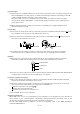
5. PARAMETERS ClassifiNo. cation Symbol 62 For manufacturer setting Do not change this value by any means. 63 Expansion parameter 2 Name and Function Initial Value Unit Setting Range 0000 400 64 100 65 1 66 1 67 0 68 0 69 0 70 0 71 0 72 0 73 0 74 0 75 0 5.3 Analog monitor The servo status can be output to two channels in terms of voltage. The servo status can be monitored using an ammeter. (1) Setting Change the following digits of parameter No. 22. Parameter No.
5. PARAMETERS (2) Setting description The servo amplifier is factory-set to output the servo motor speed to analog monitor (MO1) and the torque to analog monitor (MO2). The setting can be changed as listed below by changing the parameter No. 22 (Analog monitor output) value. Refer to (3) in this section for the measurement point. Setting 0 Output item Description Servo motor speed 8[V] Setting 6 CCW direction Output item Droop pulses ( 10V/128pulse) Description 10[V] 128[pulse] Max. speed 0 Max.
Command pulse Differential Speed command Droop pulse Position control Speed command 5 - 16 Servo motor speed Differential Speed control Current command Torque Current control Encoder M Servo Motor Position feedback Current feedback PWM Current encoder Bus voltage 5.
5. PARAMETERS 5.4 Replacement of MR-J2- B by MR-J2S- B When using the MR-J2S- B on the servo system controller peripheral software incompatible with the MR-J2S- B, you cannot use some parameter functions. Read this section carefully and set appropriate values in the parameters. 5.4.1 Main modifications made to the parameters The following table lists the parameters whose settings have been modified from the MR-J2- B or added to the MR-J2S- B.
5. PARAMETERS 5.4.2 Explanation of the modified parameters (1) Feedback pulse number (parameter No. 6) This parameter was newly added to the MR-J2S- B. If the peripheral software of the servo system controller is not compatible with the MR-J2S- B, this parameter setting cannot be changed. When the servo motor used is the HC-KFS or HC-MFS, the feedback pulse number is 8192 pulses/rev, and when it is the HC-SFS, HC-RFS or HC-UFS, the feedback pulse number is 16384 pulses/rev. (2) Auto tuning (parameter No.
5. PARAMETERS (4) Machine resonance suppression filter 1 (parameter No. 18) The settings of this parameter were changed for the MR-J2S- B. If the peripheral software of the servo system controller is not compatible with the MR-J2S- B, the parameter settings are as indicated below. The notch depth is 40dB. 0 0 0 Notch frequency selection Set value Frequency 0 1 2 3 4 5 6 7 Invalid 4500 2250 1500 1125 900 750 642.
5.
6. GENERAL GAIN ADJUSTMENT 6. GENERAL GAIN ADJUSTMENT 6.1 Different adjustment methods 6.1.1 Adjustment on a single servo amplifier The gain adjustment in this section can be made on a single servo amplifier. For gain adjustment, first execute auto tuning mode 1. If you are not satisfied with the results, execute auto tuning mode 2, manual mode 1 and manual mode 2 in this order. (1) Gain adjustment mode explanation Gain adjustment mode Parameter No.
6. GENERAL GAIN ADJUSTMENT (2) Adjustment sequence and mode usage START Usage Interpolation made for 2 or more axes? Yes Interpolation mode No Operation Allows adjustment by merely changing the response level setting. First use this mode to make adjustment. Auto tuning mode 1 Operation Yes No OK? No Operation Yes OK? Used when the conditions of auto tuning mode 1 are not met and the load inertia moment ratio could not be estimated properly, for example.
6. GENERAL GAIN ADJUSTMENT 6.1.2 Adjustment using MR Configurator (servo configuration software) POINT When using the machine analyzer, set the servo amplifier's axis number for "F". (Refer to section 3.11.) This section gives the functions and adjustment that may be performed by using the servo amplifier with the MR Configurator (servo configuration software) which operates on a personal computer.
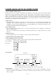
6. GENERAL GAIN ADJUSTMENT 6.2 Auto tuning 6.2.1 Auto tuning mode The servo amplifier has a real-time auto tuning function which estimates the machine characteristic (load inertia moment ratio) in real time and automatically sets the optimum gains according to that value. This function permits ease of gain adjustment of the servo amplifier. (1) Auto tuning mode 1 The servo amplifier is factory-set to the auto tuning mode 1.
6. GENERAL GAIN ADJUSTMENT 6.2.2 Auto tuning mode operation The block diagram of real-time auto tuning is shown below. Load inertia moment Automatic setting Command Encoder Control gains PG1,VG1 PG2,VG2,VIC Current control Servo motor Current feedback Set 0 or 1 to turn on. Load inertia moment ratio Switch estimation section Gain table Parameter No.9 Parameter No.8 1 5 Real-time auto tuning section Position/speed feedback Speed feedback Parameter No.
6. GENERAL GAIN ADJUSTMENT 6.2.3 Adjustment procedure by auto tuning Since auto tuning is made valid before shipment from the factory, simply running the servo motor automatically sets the optimum gains that match the machine. Merely changing the response level setting value as required completes the adjustment. The adjustment procedure is as follows. Auto tuning adjustment Acceleration/deceleration repeated Yes Load inertia moment ratio estimation value stable? No Auto tuning conditions not satisfied.
6. GENERAL GAIN ADJUSTMENT 6.2.4 Response level setting in auto tuning mode Set the response (parameter No. 9) of the whole servo system. As the response level setting is increased, the track ability and settling time for a command decreases, but a too high response level will generate vibration. Hence, make setting until desired response is obtained within the vibration-free range.
6. GENERAL GAIN ADJUSTMENT 6.3 Manual mode 1 (simple manual adjustment) If you are not satisfied with the adjustment of auto tuning, you can make simple manual adjustment with three parameters. 6.3.1 Operation of manual mode 1 In this mode, setting the three gains of position control gain 1 (PG1), speed control gain 2 (VG2) and speed integral compensation (VIC) automatically sets the other gains to the optimum values according to these gains.
6. GENERAL GAIN ADJUSTMENT (c) Adjustment description 1) Speed control gain 2 (parameter No. 16) This parameter determines the response level of the speed control loop. Increasing this value enhances response but a too high value will make the mechanical system liable to vibrate. The actual response frequency of the speed loop is as indicated in the following expression.
6. GENERAL GAIN ADJUSTMENT (c) Adjustment description 1) Position control gain 1 (parameter No. 13) This parameter determines the response level of the position control loop. Increasing position control gain 1 improves track ability to a position command but a too high value will make overshooting liable to occur at the time of settling.
6. GENERAL GAIN ADJUSTMENT 6.4 Interpolation mode The interpolation mode is used to match the position control gains of the axes when performing the interpolation operation of servo motors of two or more axes for an X-Y table or the like. In this mode, the position control gain 1 and speed control gain 1 which determine command track ability are set manually and the other gain adjusting parameters are set automatically.
6. GENERAL GAIN ADJUSTMENT 6.5 Differences in auto tuning between MELSERVO-J2 and MELSERVO-J2-Super 6.5.1 Response level setting To meet higher response demands, the MELSERVO-J2-Super series has been changed in response level setting range from the MELSERVO-J2 series. The following table lists comparison of the response level setting. Parameter No.
7. SPECIAL ADJUSTMENT FUNCTIONS 7. SPECIAL ADJUSTMENT FUNCTIONS POINT The functions given in this chapter need not be used generally. Use them if you are not satisfied with the machine status after making adjustment in the methods in chapter 6. If a mechanical system has a natural resonance point, increasing the servo system response level may cause the mechanical system to produce resonance (vibration or unusual noise) at that resonance frequency.
7. SPECIAL ADJUSTMENT FUNCTIONS (2) Parameters Set the notch frequency and notch depth of the machine resonance suppression filter 1 (parameter No. 18). Parameter No. 18 Notch frequency selection Setting Frequency Setting Frequency Setting Frequency Setting Frequency 00 Invalid 08 562.5 10 281.3 18 01 4500 09 500 11 264.7 19 180 02 2250 0A 450 12 250 1A 173.1 03 1500 0B 409.1 13 236.8 1B 166.7 04 1125 0C 375 14 225 1C 160.1 05 900 0D 346.2 15 214.3 1D 155.
7. SPECIAL ADJUSTMENT FUNCTIONS 7.3 Adaptive vibration suppression control (1) Function Adaptive vibration suppression control is a function in which the servo amplifier detects machine resonance and sets the filter characteristics automatically to suppress mechanical system vibration. Since the filter characteristics (frequency, depth) are set automatically, you need not be conscious of the resonance frequency of a mechanical system.
7. SPECIAL ADJUSTMENT FUNCTIONS (2) Parameters The operation of adaptive vibration suppression control selection (parameter No. 25). Parameter No. 25 Adaptive vibration suppression control selection 0: Invalid 1: Valid Machine resonance frequency is always detected to generate the filter in response to resonance, suppressing machine vibration. 2: Held Filter characteristics generated so far is held, and detection of machine resonance is stopped.
7. SPECIAL ADJUSTMENT FUNCTIONS 7.5 Gain changing function This function can change the gains. You can change between gains during rotation and gains during stop or can use an external signal to change gains during operation. 7.5.1 Applications This function is used when. (1) You want to increase the gains during servo lock but decrease the gains to reduce noise during rotation. (2) You want to increase the gains during settling to shorten the stop settling time.
7. SPECIAL ADJUSTMENT FUNCTIONS 7.5.3 Parameters When using the gain changing function, always set " 2 " in parameter No.8 (auto tuning) to choose the manual mode 2 of the gain adjustment modes. The gain changing function cannot be used in the auto tuning mode. Parameter Abbrevi No. ation Name Unit Description Position and speed gains of a model used to set the response level to a command. Always valid.
7. SPECIAL ADJUSTMENT FUNCTIONS (1) Parameters No. 12 to 17 These parameters are the same as in ordinary manual adjustment. Gain changing allows the values of ratio of load inertia moment to servo motor inertia moment, position control gain 2, speed control gain 2 and speed integral compensation to be changed. (2) Ratio of load inertia moment to servo motor inertia moment 2 (parameter No. 52) Set the ratio of load inertia moment to servo motor inertia moment after changing.
7. SPECIAL ADJUSTMENT FUNCTIONS 7.5.4 Gain changing operation This operation will be described by way of setting examples. (1) When you choose changing by external input (a) Setting Parameter No. Abbreviation Setting Unit 13 PG1 Position control gain 1 Name 100 rad/s 14 VG1 Speed control gain 1 1000 rad/s 12 GD2 Ratio of load inertia moment to servo motor inertia moment 4 0.
7. SPECIAL ADJUSTMENT FUNCTIONS (2) When you choose changing by droop pulses (a) Setting Parameter No. Abbreviation Setting Unit 13 PG1 Position control gain 1 Name 100 rad/s 14 VG1 Speed control gain 1 1000 rad/s 12 GD2 Ratio of load inertia moment to servo motor inertia moment 40 0.1 times 15 PG2 Position control gain 2 120 rad/s 16 VG2 Speed control gain 2 3000 rad/s 17 VIC Speed integral compensation 20 ms 100 0.
7.
8. INSPECTION 8. INSPECTION WARNING Before starting maintenance and/or inspection, turn off the power and wait for 15 minutes or more until the charge lamp turns off. Then, confirm that the voltage between P and N is safe with a voltage tester and others. Otherwise, an electric shock may occur. In addition, always confirm from the front of the servo amplifier whether the charge lamp is off or not. Any person who is involved in inspection should be fully competent to do the work.
8.
9. TROUBLESHOOTING 9. TROUBLESHOOTING 9.1 Alarms and warning list When a fault occurs during operation, the corresponding alarm or warning is displayed. If any alarm or warning has occurred, refer to section 9.2 or 9.3 and take the appropriate action. After its cause has been removed, the alarm can be deactivated in any of the methods marked in the alarm deactivation column.
9. TROUBLESHOOTING 9.2 Remedies for alarms CAUTION When any alarm has occurred, eliminate its cause, ensure safety, then reset the alarm, and restart operation. Otherwise, injury may occur. If an absolute position erase alarm (25) occurred, always make home position setting again. Otherwise, misoperation may occur. As soon as an alarm occurs, mark Servo-off and power off the main circuit and control circuit.
9. TROUBLESHOOTING Display 15 Name Definition Memory error 2 EEP-ROM fault Cause Action 1. Faulty parts in the servo amplifier Change the servo amplifier. Checking method Alarm (15) occurs if power is switched on after disconnection of all cables but the control circuit power supply cables. 2. The number of write times to EEPROM exceeded 100,000. 16 17 Encoder error 1 Communication 1. Encoder connector (CN2) error occurred disconnected. between encoder 2. Encoder fault and servo amplifier. 3.
9. TROUBLESHOOTING Display Name 30 Regenerative error Definition Cause Permissible 1. Mismatch between used regenerative power regenerative option and of the built-in parameter No. 2 setting regenerative 2. Built-in regenerative resistor or resistor or regenerative option is not regenerative option connected. is exceeded. 3. High-duty operation or continuous regenerative operation caused the permissible regenerative power of the regenerative option to be exceeded. Action Set correctly. Connect correctly.
9. TROUBLESHOOTING Display 33 Name Overvoltage Definition Converter bus voltage exceeded 400VDC. Cause 1. Regenerative option is not used. Action Use the regenerative option. 2. Though the regenerative option is Make correct setting. used, the parameter No. 2 setting is " 00 (not used)". 3. Lead of built-in regenerative resistor or regenerative option is open or disconnected. 1. Change the lead. 2. Connect correctly. 4. Regenerative transistor faulty. Change the servo amplifier. 5.
9. TROUBLESHOOTING Display 46 50 Name Servo motor overheat Overload 1 Definition Servo motor temperature rise actuated the thermal sensor. Load exceeded overload protection characteristic of servo amplifier. Cause Action 1. Ambient temperature of servo motor is over 40 (104 ). Review environment so that ambient temperature is 0 to 40 (32 to 104 ). 2. Servo motor is overloaded. 1. Reduce load. 2. Review operation pattern. 3. Use servo motor that provides larger output. 3.
9. TROUBLESHOOTING Display 52 Name Definition (Note) The deviation Error excessive between the model position and the actual servo motor position exceeds the parameter No.31 setting value (initial value: 2 revolutions). Cause Action 1. Acceleration/deceleration time constant is too small. Increase the acceleration/deceleration time constant. 2. Torque limit value is too small. Increase the torque limit value. 3. Motor cannot be started due to torque shortage caused by power supply voltage drop.
9. TROUBLESHOOTING 9.3 Remedies for warnings POINT When any of the following alarms has occurred, do not resume operation by switching power of the servo amplifier OFF/ON repeatedly. The servo amplifier and servo motor may become faulty. If the power of the servo amplifier is switched OFF/ON during the alarms, allow more than 30 minutes for cooling before resuming operation.
10. OUTLINE DIMENSION DRAWINGS 10. OUTLINE DIMENSION DRAWINGS 10.1 Servo amplifiers (1) MR-J2S-10B to MR-J2S-60B MR-J2S-10B1 to MR-J2S-40B1 [Unit: mm] 6 ( 0.24) mounting hole 70 (2.76) 20 B 6 (0.24) ([Unit: in]) 135 (5.32) Terminal layout (Terminal cover open) (0.79) A MITSUBISHI MITSUBISHI OPEN C N 1 A C N 1 B C N 2 E N C C N 3 Rating plate TE1 C N 1 A C N 1 B C N 2 C N 3 ( 168 (6.61) 156 (6.14) OPEN ) E N C 6 (0.24) 7 (0.28) L1 L2 L3 (Note) U V W TE2 PE terminal 6 (0.
10. OUTLINE DIMENSION DRAWINGS (2) MR-J2S-70B MR-J2S-100B [Unit: mm] 70(2.76) 70(2.76) 20 6 (0.24) 22 (0.87) ([Unit: in]) 190(7.48) Terminal layout (0.79) 6 ( 0.24) mounting hole (Terminal cover open) MITSUBISHI MITSUBISHI OPEN 7 (0.28) 6(0.24) 156(6.14) 168(6.61) OPEN C N 1 A C N 1 B C N 2 E N C C N 3 L1 L2 L3 U V W Rating plate PE terminal 6(0.24) 22 42 (0.87) (1.65) TE2 TE1 6(0.24) 6(0.24) Mass [kg]([lb]) Servo amplifier MR-J2S-70B 1.7 (3.
10. OUTLINE DIMENSION DRAWINGS (3) MR-J2S-200B MR-J2S-350B [Unit: mm] ([Unit: in]) 70(2.76) 90(3.54) 78(3.07) 6 (0.24) 195(7.68) 6 (0.24) 2- 6 ( 0.24) mounting hole Terminal layout MITSUBISHI 168(6.61) 156(6.14) MITSUBISHI TE2 TE1 PE terminal Cooling fan wind direction Mass [kg]([lb]) Servo amplifier MR-J2S-200B 2.0 (4.41) MR-J2S-350B Terminal signal layout PE terminals TE1 L1 L2 L3 U V W Terminal screw: M4 Tightening torque: 1.2 [N m] (10.
10. OUTLINE DIMENSION DRAWINGS (4) MR-J2S-500B [Unit: mm] ([Unit: in]) 20 (0.24) 130(5.12) (0.24) 70 6 6 (2.76) 118(4.65) OPEN (0.79) 7.5 (0.5) 2- 6 ( 0.24) mounting hole 200(7.87) (0.19) 5 MITSUBISHI 235(9.25) 250(9.84) OPEN OPEN TE1 C N 1 A C N 1 B C N 1 A C N 1 B C N 2 C N 3 C N 2 C N 3 TE2 N.P. N.P. 7.5 (0.5) Terminal layout MITSUBISHI 6(0.24) Cooling fan Cooling fan wind direction Servo amplifier Mass [kg]([lb]) MR-J2S-500B 4.9(10.
10. OUTLINE DIMENSION DRAWINGS (5) MR-J2S-700B 70 10 (2.76) 180(7.09) 160(6.23) 350(13.8) 335(13.2) (0.39) 200(7.87) 138(5.43) 62 20 7.5 (0.5) (0.39) 10 (0.79) 2- 6( 0.24) mounting hole (2.44) [Unit: mm] ([Unit: in]) 6(0.24) Terminal layout MITSUBISHI MITSUBISHI OPEN OPEN C N 1 A C N 1 B C N 1 A C N 1 B C N 2 C N 3 C N 2 C N 3 TE2 OPEN TE1 7.5 (0.5) 6 (0.24) Cooling fan Servo amplifier Mass [kg]([lb]) MR-J2S-700B 7.2(15.
10. OUTLINE DIMENSION DRAWINGS (6) MR-J2S-11KB 15KB 12(0.47) [Unit: mm] ([Unit: in]) 2- 12( 0.47) mounting hole 75 (2.95) Cooling fan wind direction MITSUBISHI C N 3 C N 1 A C N 1 B 400(15.75) 376(14.8) CN4 Cooling fan TE2 CN2 CON2 CHARGE Mass [kg]([lb]) MR-J2S-11KB 15(33.1) MR-J2S-15KB 16(35.3) 260(10.24) 12(0.47) 3.9(0.15) Servo amplifier (0.47) 12(0.47) 236(9.29) 260(10.24) (0.
10. OUTLINE DIMENSION DRAWINGS (7) MR-J2S-22KB 12(0.47) [Unit: mm] ([Unit: in]) 2- 12( 0.47) mounting hole Coolig fan wind direction 75 (2.95) MITSUBISHI C N 3 C N 1 A C N 1 B 400(15.75) Cooling fan 376(14.8) CN4 TE2 CON2 CN2 CHARGE 12 12(0.47) 326(12.84) 350(13.78) 12(0.47) 3.9(0.15) 260(0.24) (0.47)12 (0.47) TE1 Servo amplifier Mass [kg]([lb]) MR-J2S-22KB 20(44.
10. OUTLINE DIMENSION DRAWINGS 10.2 Connectors (1) Servo amplifier side <3M> (a) Soldered type Model Connector Shell kit : 10120-3000PE 10126-3000PE : 10320-52F0-008 10326-52F0-008 [Unit: mm] ([Unit: in]) 10.0 (0.39) 12.0(0.47) 14.0 (0.55) Logo, etc. are indicated here. 39.0(1.54) 23.8(0.94) A B 12.7 (0.50) Connector Shell kit 10120-3000PE 10126-3000PE Variable dimensions A B 10320-52F0-008 22.0(0.87) 33.3(1.31) 10326-52F0-008 25.8(1.02) 37.2(1.
10. OUTLINE DIMENSION DRAWINGS (c) Insulation displacement type Model Connector Shell kit : 10120-6000EL : 10320-3210-000 11.5 (0.45) [Unit: mm] 6.7 ( 0.26) ([Unit: in]) 2- 0.5 (0.02) Logo, etc. are indicated here. 42.0(1.65) 33.0(1.30) 20.9(0.82) 29.7 (1.17) (2) Bus cable connector (a) Honda Tsushin Industry PCR type PCR-LS20LA1 PCR-LS20LA1W 13.0 10.4(0.41) (0.51) (0.04)1 12.2 1(0.04) (0.48) HONDA RS 27.4(1.08) 32.0(0.91) 27.4(1.08) 32.0(0.91) 1.9 1 12.2 1 (0.08) (0.04)(0.48) (0.
10. OUTLINE DIMENSION DRAWINGS (b) Honda Tsushin Industry HDR type Model HDR Number of Pins Connector Connector case 14 HDR-E14MG1 HDR-E14LPA5 26 HDR-E26MG1 HDR-E26LPA5 (Note) Crimping terminal Wire straightening tool : FHAT-0029 Insulation displacement tool : FHPT-0004C Note. Not available from us and to be supplied by the customer. Model Connector : HDR-E26MG1 Connector case : HDR-E26LPA5 Model Connector : HDR-E14MG1 Connector case : HDR-E14LPA5 [Unit: mm] ([Unit: in]) 21.8 (0.86) 6 7 (0.
11. CHARACTERISTICS 11. CHARACTERISTICS 11.1 Overload protection characteristics An electronic thermal relay is built in the servo amplifier to protect the servo motor and servo amplifier from overloads. Overload 1 alarm (50) occurs if overload operation performed is above the electronic thermal relay protection curve shown in any of Figs 11.1, Overload 2 alarm (51) occurs if the maximum current flew continuously for several seconds due to machine collision, etc.
11. CHARACTERISTICS 11.2 Power supply equipment capacity and generated loss (1) Amount of heat generated by the servo amplifier Table 11.1 indicates servo amplifiers' power supply capacities and losses generated under rated load. For thermal design of an enclosure, use the values in Table 11.1 in consideration for the worst operating conditions. The actual amount of generated heat will be intermediate between values at rated torque and servo off according to the duty used during operation.
11. CHARACTERISTICS Servo amplifier MR-J2S-500B MR-J2S-700B MR-J2S-11KB MR-J2S-15KB MR-J2S-22KB Servo motor (Note 1) Power supply capacity[kVA] (Note 2) Servo amplifier-generated heat[W] Area required for heat dissipation At rated torque With servo off [m2] [ft2] HC-SFS502 7.5 195 25 3.9 42.0 HC-RFS353 5.5 135 25 2.7 29.1 HC-RFS503 7.5 195 25 3.9 42.0 HC-UFS352 5.5 195 25 3.9 42.0 HC-UFS502 7.5 195 25 3.9 42.0 HC-LFS302 4.5 120 25 2.4 25.8 HA-LFS502 7.
11. CHARACTERISTICS (2) Heat dissipation area for enclosed servo amplifier The enclosed control box (hereafter called the control box) which will contain the servo amplifier should be designed to ensure that its temperature rise is within 10 at the ambient temperature of 40 . (With a 5 (41 ) safety margin, the system should operate within a maximum 55 (131 ) limit.) The necessary enclosure heat dissipation area can be calculated by Equation 11.1. A P K T ................................................
11. CHARACTERISTICS 11.3 Dynamic brake characteristics 11.3.1 Dynamic brake operation (1) Calculation of coasting distance Fig. 11.3 shows the pattern in which the servo motor comes to a stop when the dynamic brake is operated. Use Equation 11.2 to calculate an approximate coasting distance to a stop. The dynamic brake time constant varies with the servo motor and machine operation speeds. (Refer to (2) in this section.) Forced stop(EM1) ON OFF Time constant V0 Machine speed Time te Fig. 11.
11.
11. CHARACTERISTICS 11.3.2 The dynamic brake at the load inertia moment Use the dynamic brake under the load inertia moment ratio indicated in the following table. If the load inertia moment is higher than this value, the built-in dynamic brake may burn. If there is a possibility that the load inertia moment may exceed the value, contact Mitsubishi.
11. CHARACTERISTICS 11.5 Inrush currents at power-on of main circuit and control circuit The following table indicates the inrush currents (reference value) that will flow when the maximum permissible voltage (253VAC) is applied at the power supply capacity of 2500kVA and the wiring length of 10m. Servo amplifier Inrush Currents (A0-p) Main circuit power supply (L1, L2, L3) MR-J2S-10B 20B 30A (Attenuated to approx. 5A in 10ms) MR-J2S-40B 60B 30A (Attenuated to approx.
12. OPTIONS AND AUXILIARY EQUIPMENT 12. OPTIONS AND AUXILIARY EQUIPMENT WARNING Before connecting any option or peripheral equipment, turn off the power and wait for 15 minutes or more until the charge lamp turns off. Then, confirm that the voltage between P and N is safe with a voltage tester and others. Otherwise, an electric shock may occur. In addition, always confirm from the front of the servo amplifier whether the charge lamp is off or not.
12. OPTIONS AND AUXILIARY EQUIPMENT (2) Selection of the regenerative option (a) Simple selection method In horizontal motion applications, select the regenerative option as described below. When the servo motor is run without load in the regenerative mode from the running speed to a stop, the permissible duty is as indicated in section 5.1 of the separately available Servo Motor Instruction Manual.
12. OPTIONS AND AUXILIARY EQUIPMENT b. Losses of servo motor and servo amplifier in regenerative mode The following table lists the efficiencies and other data of the servo motor and servo amplifier in the regenerative mode.
12. OPTIONS AND AUXILIARY EQUIPMENT (4) Connection of the regenerative option POINT When the MR-RB50 MR-RB51 is used, a cooling fan is required to cool it. The cooling fan should be prepared by the customer. The regenerative option will generate heat of about 100 . Fully examine heat dissipation, installation position, used cables, etc. before installing the option. For wiring, use flame-resistant cables and keep them clear of the regenerative option body. Always use twisted cables of max. 5m(16.
12. OPTIONS AND AUXILIARY EQUIPMENT (b) MR-J2S-500B MR-J2S-700B Always remove the wiring (across P-C) of the servo amplifier built-in regenerative resistor and fit the regenerative option across P-C. The G3 and G4 terminals act as a thermal sensor. G3-G4 is opened when the regenerative option overheats abnormally. Servo amplifier Always remove wiring (across P-C) of servo amplifier built-in regenerative resistor. Regenerative option P P C C G3 (Note 2) G4 5m(16.
12. OPTIONS AND AUXILIARY EQUIPMENT For the MR-RB50 MR-RB51 install the cooling fan as shown. [Unit : mm(in)] Cooling fan installation screw hole dimensions 2-M3 screw hole Top Bottom 82.5 82.5 (3.25) Thermal relay 133 (for cooling fan installation) Depth 10 or less (Screw hole already machined) Terminal block (5.24) Cooling fan 40 (1.58) (3.
12. OPTIONS AND AUXILIARY EQUIPMENT (d) MR-J2S-11KB-PX to MR-J2S-22KB-PX (when using the regenerative option) The MR-J2S-11KB-PX to MR-J2S-22KB-PX servo amplifiers are not supplied with regenerative resistors. When using any of these servo amplifiers, always use the MR-RB65, 66 or 67 regenerative option. The MR-RB65, 66 and 67 are regenerative options that have encased the GRZG400-2Ω, GRZG4001Ω and GRZG400-0.8Ω, respectively.
12. OPTIONS AND AUXILIARY EQUIPMENT (5) Outline drawing (a) MR-RB032 MR-RB12 [Unit: mm (in)] LA TE1 Terminal block 5 (0.20) G3 G4 P C 6 (0.24) 12 (0.47) G3 G4 P C 6 (0.24) TE1 168 (6.61) 156 (6.14) MR-RB 144 (5.67) 12 (0.47) 6 (0.24) 6 (0.24) mounting hole LB Terminal screw: M3 1.6 (0.06) 20 (0.79) LD LC Tightening torque: 0.5 to 0.6 [N m](4 to 5 [lb in]) Mounting screw Screw size: M5 Tightening torque: 3.24 [N m](28.
12. OPTIONS AND AUXILIARY EQUIPMENT (c) MR-RB50 MR-RB51 [Unit: mm (in)] Fan mounting screw (2-M3 screw) On opposite side 49 (1.93) Terminal block P C Terminal screw: M4 G3 Tightening torque: 1.2 [N m] (10.6 [Ib in]) G4 82.5 (3.25) 7 14 slot Mounting screw Screw: M6 Tightening torque: 5.4 [N m] Wind blows in the arrow direction (47.79 [Ib in]) Regenerative option MR-RB50 2.3 (0.09) 200 (7.87) 217 (8.54) 17 (0.67) 12 (0.47) 7 (0.28) 108 (4.25) 120 (4.72) MR-RB51 Mass [kg] (Ib) 5.6 (12.
12. OPTIONS AND AUXILIARY EQUIPMENT 12.1.2 FR-BU2 brake unit POINT The brake unit and resistor unit of other than 200V class are not applicable to the servo amplifier. Combination of different voltage class units and servo amplifier cannot be used. Install a brake unit and a resistor unit on a flat surface vertically. When the unit is installed horizontally or diagonally, the heat dissipation effect diminishes. Temperature of the resistor unit case rises to higher than 100 .
12. OPTIONS AND AUXILIARY EQUIPMENT (2) Brake unit parameter setting Normally, when using the FR-BU2, changing parameters is not necessary. Whether a parameter can be changed or not is listed below. Change possible/ impossible Parameter No.
12. OPTIONS AND AUXILIARY EQUIPMENT Note 1. For power supply specifications, refer to section 1.3. 2. For the servo amplifier of 5k and 7kW, always disconnect the lead of built-in regenerative resistor, which is connected to the P and C terminals. For the servo amplifier of 11k to 22kW, do not connect a supplied regenerative resistor to the P and C terminals. 3. For the servo amplifier of 11k to 22kW, always connect P1 and P (Factory-wired).
12. OPTIONS AND AUXILIARY EQUIPMENT (c) Precautions for wiring The cables between the servo amplifier and the brake unit, and between the resistor unit and the brake unit should be as short as possible. Always twist the cable longer than 5m (twist five times or more per one meter). Even when the cable is twisted, the cable should be less than 10m. Using cables longer than 5m without twisting or twisted cables longer than 10m, may result in the brake unit malfunction.
12. OPTIONS AND AUXILIARY EQUIPMENT (e) Crimping terminals for P and N terminals of servo amplifier POINT Always use recommended crimping terminals or equivalent since some crimping terminals cannot be installed depending on the size. Servo amplifier Brake unit Number of connected units Crimping terminal (Manufacturer) MR-J2S-350B FR-BU2-15K 1 FVD5.
12. OPTIONS AND AUXILIARY EQUIPMENT FR-BU2-30K 2- 5 hole (Screw size: M4) Rating plate 6 5 96 108 5 6 18.5 52 129.5 59 FR-BU2-55K 2- 5 hole (Screw size: M4) Rating plate 5 5 6 158 170 12 - 15 6 18.5 52 72 142.
12. OPTIONS AND AUXILIARY EQUIPMENT (b) FR-BR resistor unit [Unit: mm] 2 C (Note) Control circuit terminal (Note) Main circuit terminal C C Approx. 35 W1 Approx. 35 1 For FR-BR-55K, a hanging bolt is placed on two locations (Indicated below). Hanging bolt W 204 5 Note. Ventilation ports are provided on both sides and the top. The bottom is open. W W1 H H1 H2 H3 D D1 C Approximate mass [kg] ([lb]) FR-BR-15K 170 100 450 410 20 432 220 3.2 6 15 (33.
12. OPTIONS AND AUXILIARY EQUIPMENT 12.1.3 Power regeneration converter When using the power regeneration converter, set " 01" in parameter No.2. Power Nominal regeneration regenerative power converter (kW) FR-RC-15K 15 FR-RC-30K 30 FR-RC-55K 55 Continuous energization time [sec] (1) Selection The converters can continuously return 75% of the nominal regenerative power. They are applied to the servo amplifiers of the MR-J2S-500B to MR-J2S-22KB.
12. OPTIONS AND AUXILIARY EQUIPMENT (2) Connection example Servo amplifier L11 NFB L21 (Note 3) Power factor improving reactor FR-BAL MC L1 (Note 5) Power supply L2 L3 VDD COM EM1 SG (Note 2) N RDY Ready N/ C P P/ P1 5m(16.4ft) or less (Note 4) A SE RDY output R/L1 S/L2 B B C C Alarm output T/L3 RX R SX S (Note 1) Phase detection terminals TX T Power regeneration converter FR-RC FR-RC B C Operation ready RA2 EM1 OFF ON MC MC SK Note 1.
12. OPTIONS AND AUXILIARY EQUIPMENT (3) Outside dimensions of the power regeneration converters [Unit : mm(in)] E 2- D hole Mounting foot (removable) Mounting foot movable Rating plate Display panel window BA B Front cover Cooling fan D K F EE AA C A Heat generation area outside mounting dimension Power regeneration converter A AA B BA C D E EE K F Approx. mass [kg(Ib)] FR-RC-15K 270 (10.6) 200 (7.87) 450 (17.7) 432 (17.0) 195 (7.68) 10 (0.39) 10 (0.39) 8 (0.32) 3.2 (0.
12. OPTIONS AND AUXILIARY EQUIPMENT 12.1.4 External dynamic brake POINT Configure up a sequence which switches off the contact of the brake unit after (or as soon as) it has turned off the servo on signal at a power failure or failure. For the braking time taken when the dynamic brake is operated, refer to section 13.3. The brake unit is rated for a short duration. Do not use it for high duty.
12. OPTIONS AND AUXILIARY EQUIPMENT (2) Connection example Servo amplifier (Note 1) EM1 Operation-ready ON OFF MC CON2 15 VDD MC SK NFB 18 COM 4 DB RA1 MC Servo motor L1 (Note 4) Power supply L2 U L3 V L11 W U V E L21 (Note 3) P P1 M W CON2 2 EM1 1 SG Plate SD EM1 (Note 2) 14 13 U V W a RA1 b Dynamic brake Note 1. Configure up the circuit to switch power off in the external sequence at servo alarm occurrence. 2. Terminals 13, 14 are normally open contact outputs.
12. OPTIONS AND AUXILIARY EQUIPMENT (3) Outline dimension drawing [Unit: mm] ([Unit: in]) D (0.2)5 100(3.94) A E B E 5 (0.2) G D C Terminal block E a (GND) 2.3(0.09) F U b 13 14 V W Screw : M4 Screw : M3.5 Tightening torque: 0.8 [N m](7 [lb in]) Tightening torque: 1.2 [N m](10.6 [lb in]) Dynamic brake A B C D E F G Mass [kg]([Ib]) Connection wire [mm2] DBU-11K 200 (7.87) 190 (7.48) 140 (5.51) 20 (0.79) 5 (0.2) 170 (6.69) 163.5 (6.44) 2 (4.41) 5.
12. OPTIONS AND AUXILIARY EQUIPMENT 12.1.5 Cables and connectors (1) Cable make-up The following cables are used for connection with the servo motor and other models. The broken line areas in the diagram are not options.
12. OPTIONS AND AUXILIARY EQUIPMENT No. Product Model Description Connector: 10120-3000PE Shell kit: 10320-52F0-008 (3M or equivalent) Housing: 1-172161-9 Connector pin: 170359-1 (AMP or equivalent) Cable clamp: MTI-0002 (Toa Electric Industry) Application Standard flexing life IP20 1) Standard encoder MR-JCCBL M-L cable Refer to (2) in this section.
12. OPTIONS AND AUXILIARY EQUIPMENT No.
12. OPTIONS AND AUXILIARY EQUIPMENT No. Product 24) Bus cable Model Q172J2BCBL M (-B) Refer to (4) in this section Description Connector: HDR-E14MG1 Shell kit: HDR-E14LPA5 (Honda Tsushin) Connector: 10120-6000EL Shell kit: 10320-3210-000 (3M or equivalent) (Note) Socket: HCN2-2.5S-2 Terminal: HCN2-2.5S-D-B (Hirose Electric) Note. When using the battery unit Q170BAT, use the Q172J2BCBL M-B.
12. OPTIONS AND AUXILIARY EQUIPMENT (2) Encoder cable CAUTION If you have fabricated the encoder cable, connect it correctly. Otherwise, misoperation or explosion may occur. POINT The encoder cable is not oil resistant. Refer to section 11.4 for the flexing life of the encoder cable. When the encoder cable is used, the sum of the resistance values of the cable used for P5 and the cable used for LG should be within 2.4 .
12.
12. OPTIONS AND AUXILIARY EQUIPMENT (b) MR-JHSCBL M-L MR-JHSCBL M-H MR-ENCBL M-H These encoder cables are used with the HC-SFS HC-RFS HC-UFS2000r/min series servo motors. 1) Model explanation Model: MR-JHSCBL MSymbol L H Specifications Standard flexing life Long flexing life Symbol (Note) Cable length [m(ft)] 2 2 (6.56) 5 5 (16.4) 10 10 (32.8) 20 20 (65.6) 30 30 (98.4) 40 40 (131.2) 50 50 (164.0) Note. MR-JHSCBL M-L has no 40(131.2ft) and 50m(164.0ft) sizes.
12.
12. OPTIONS AND AUXILIARY EQUIPMENT (3) Communication cable POINT This cable may not be used with some personal computers. After fully examining the signals of the RS-232C connector, refer to this section and fabricate the cable.
12. OPTIONS AND AUXILIARY EQUIPMENT (4) Bus cable CAUTION When fabricating the bus cable, do not make incorrect connection. Doing so can cause misoperation or explosion. When fabricating this cable, use the recommended cable given in section 12.2.1 and fabricate it in accordance with the connection diagram shown in this section. The overall distance of the bus cable on the same bus is 30m(98.4ft). (a) MR-J2HBUS M-A 1) Model definition Model: MR-J2HBUS M-A Symbol 05 1 5 Cable length [m(ft)] 0.5 (1.
12. OPTIONS AND AUXILIARY EQUIPMENT (b) MR-J2HBUS M 1) Model definition Model: MR-J2HBUS M Symbol 05 1 5 Cable length [m(ft)] 0.5 (1.64) 1 (3.28) 5 (16.
12. OPTIONS AND AUXILIARY EQUIPMENT (c) Q172J2BCBL M(-B) When using the battery unit Q170BAT, use the Q172J2BCBL M-B. For the Q170BAT, refer to the Motion Controller Q Series User's Manual (IB(NA)0300021). 1) Model definition Model: Q172J2BCBL MSymbol No -B Connection of battery unit No Yes Symbol 05 1 5 Cable length [m(ft)] 0.5 (1.64) 1 (3.28) 5 (16.
12.
12. OPTIONS AND AUXILIARY EQUIPMENT 12.1.6 Maintenance junction card (MR-J2CN3TM) POINT The MR-J2S-11KB or more allows only the relaying of signals using CN3A/CN3C. Since TE1 cannot be used, keep it open. (1) Usage The maintenance junction card (MR-J2CN3TM) is designed for use when a personal computer and analog monitor outputs are used at the same time.
12. OPTIONS AND AUXILIARY EQUIPMENT 12.1.7 Battery (MR-BAT, A6BAT) POINT The revision (Edition 44) of the Dangerous Goods Rule of the International Air Transport Association (IATA) went into effect on January 1, 2003 and was enforced immediately. In this rule, "provisions of the lithium and lithium ion batteries" were revised to tighten the restrictions on the air transportation of batteries.
12. OPTIONS AND AUXILIARY EQUIPMENT (2) System configuration (a) Components To use this software, the following components are required in addition to the servo amplifier and servo motor. Model (Note 2) Personal computer OS Display Keyboard Mouse Printer Communication cable (Note 1) Description IBM PC-AT compatible where the English version of Windows® 95, Windows® 98, Windows® Me, Windows NT® Workstation 4.
12. OPTIONS AND AUXILIARY EQUIPMENT 12.1.9 Power regeneration common converter POINT For details of the power regeneration common converter FR-CV, refer to the FR-CV Installation Guide (IB(NA)0600075). Do not supply power to the main circuit power supply terminals (L1, L2, L3) of the servo amplifier. Doing so will fail the servo amplifier and FR-CV. Connect the DC power supply between the FR-CV and servo amplifier with correct polarity.
12.
12. OPTIONS AND AUXILIARY EQUIPMENT 2) Grounding For grounding, use the wire of the size equal to or greater than that indicated in the following table, and make it as short as possible. Grounding wire size [mm2] Power regeneration common converter FR-CV-7.5K TO FR-CV-15K FR-CV-22K • FR-CV-30K FR-CV-37K • FR-CV-55K 14 22 38 (b) Example of selecting the wire sizes When connecting multiple servo amplifiers, always use junction terminals for wiring the servo amplifier terminals P, N.
12. OPTIONS AND AUXILIARY EQUIPMENT (5) Specifications Power regeneration common converter FR-CV- 7.5K 11K 15K 22K 30K 37K 55K Item Total of connectable servo amplifier capacities [kW] 3.75 5.5 7.5 11 15 18.5 27.5 Maximum servo amplifier capacity [kW] 3.
12. OPTIONS AND AUXILIARY EQUIPMENT 12.1.10 Heat sink outside mounting attachment (MR-JACN) Use the heat sink outside mounting attachment to mount the heat generation area of the servo amplifier in the outside of the control box to dissipate servo amplifier-generated heat to the outside of the box and reduce the amount of heat generated in the box, thereby allowing a compact control box to be designed.
12. OPTIONS AND AUXILIARY EQUIPMENT (3) Fitting method Attachment Fit using the assembling screws. Servo amplifier Servo amplifier Punched hole Attachment Control box a. Assembling the heat sink outside mounting attachment b. Installation to the control box (4) Outline dimension drawing (a) MR-JACN15K (MR-J2S-11KB, MR-J2S-15KB) 145 (5.709) 194 (7.638) 84 (3.307) 236 (9.291) 280 (11.024) 260 (10.236) 400 (15.748) Servo amplifier Servo amplifier 35 (1.378) 510 (20.
12. OPTIONS AND AUXILIARY EQUIPMENT (b) MR-JACN22K (MR-J2S-22KB) 145(5.709) 194(7.638) Servo amplifier 370(14.567) Servo amplifier 35(1.378) 84 (3.307) 326(12.835) 400(15.748) 58 510(20.079) Panel Attachment Attachment 12 (0.472) 580(22.835) (2.283) 68(2.677) 4- 12 Mounting hole 350(13.78) Panel 3.2(0.126) 155(6.102) 105 (4.134) 260 (10.236) 12 - 45 11.5 (0.
12. OPTIONS AND AUXILIARY EQUIPMENT 12.2 Auxiliary equipment Always use the devices indicated in this section or equivalent. To comply with the EN Standard or UL/CUL (CSA) Standard, use the products which conform to the corresponding standard. 12.2.1 Recommended wires (1) Wires for power supply wiring The following diagram shows the wires used for wiring. Use the wires given in this section or equivalent.
12. OPTIONS AND AUXILIARY EQUIPMENT Table 12.1 Recommended wires Servo amplifier MR-J2S-10B(1) MR-J2S-20B(1) MR-J2S-40B(1) MR-J2S-60B MR-J2S-70B MR-J2S-100B MR-J2S-200B (Note 1) Wires [mm2] 1) L1 L2 L3 2) L11 L21 3) U V W P1 8 (AWG8) : c 14 (AWG6) :d 2 (AWG14) : a 3.5 (AWG12) : b (Note 2) 5.5 (AWG10) : b 5.5 (AWG10) : b 8 (AWG8) : c 22 (AWG4) :e MR-J2S-15KB 22 (AWG4) :e 30 (AWG2) :f MR-J2S-22KB 50 (AWG1/0) :g 60 (AWG2/0) :g MR-J2S-350B MR-J2S-500B MR-J2S-700B MR-J2S-11KB 5.
12. OPTIONS AND AUXILIARY EQUIPMENT (2) Wires for cables When fabricating a cable, use the wire models given in the following table or equivalent. Table 12.3 Wires for option cables Type Length [m(ft)] Model MR-JCCBL MR-JCCBL Encoder cable MR-JHSCBL MR-JHSCBL MR-ENCBL M-L M-H M-L M-H M-H 2 to 10 (6.56 to 32.8) 20 30 (65.6 98.4) 2 5 (6.56 16.4) 10 to 50 (32.8 to 164) 2 5 (6.56 16.4) 10 to 30 (32.8 to 98.4) 2 5 (6.56 16.4) 10 to 50 (32.8 to 164) 2 5 (6.56 16.4) 10 to 50 (32.
12. OPTIONS AND AUXILIARY EQUIPMENT 12.2.2 No-fuse breakers, fuses, magnetic contactors Always use one no-fuse breaker and one magnetic contactor with one servo amplifier. When using a fuse instead of the no-fuse breaker, use the one having the specifications given in this section.
12. OPTIONS AND AUXILIARY EQUIPMENT 12.2.4 Power factor improving DC reactors The input power factor is improved to be about 95%. (Note 1) Terminal cover Screw size G D C or less Rating plate 2-F L Notch H B or less L E A or less F Mounting foot part 5m or less Servo amplifier FR-BEL P (Note2) P1 Note 1. Fit the supplied terminal cover after wiring. 2. When using the DC reactor, remove the short-circuit bar across P1-P.
12. OPTIONS AND AUXILIARY EQUIPMENT 12.2.5 Relays The following relays should be used with the interfaces. Interface Selection example Relay used for digital input signals (interface DI-1) To prevent defective contacts , use a relay for small signal (twin contacts). (Ex.) Omron : type G2A , MY Relay used for digital output signals (interface DO-1) Small relay with 12VDC or 24VDC of 40mA or less (Ex.) Omron : type MY 12.2.6 Surge absorbers A surge absorber is required for the electromagnetic brake.
12. OPTIONS AND AUXILIARY EQUIPMENT 12.2.7 Noise reduction techniques Noises are classified into external noises which enter the servo amplifier to cause it to malfunction and those radiated by the servo amplifier to cause peripheral devices to malfunction. Since the servo amplifier is an electronic device which handles small signals, the following general noise reduction techniques are required. Also, the servo amplifier can be a source of noise as its outputs are chopped by high carrier frequencies.
12. OPTIONS AND AUXILIARY EQUIPMENT (c) Techniques for noises radiated by the servo amplifier that cause peripheral devices to malfunction Noises produced by the servo amplifier are classified into those radiated from the cables connected to the servo amplifier and its main circuits (input and output circuits), those induced electromagnetically or statically by the signal cables of the peripheral devices located near the main circuit cables, and those transmitted through the power supply cables.
12. OPTIONS AND AUXILIARY EQUIPMENT Noise transmission route Suppression techniques 1) 2) 3) When measuring instruments, receivers, sensors, etc. which handle weak signals and may malfunction due to noise and/or their signal cables are contained in a control box together with the servo amplifier or run near the servo amplifier, such devices may malfunction due to noises transmitted through the air. The following techniques are required.
12. OPTIONS AND AUXILIARY EQUIPMENT (b) Surge suppressor The recommended surge suppressor for installation to an AC relay, AC valve, AC electromagnetic brake or the like near the servo amplifier is shown below. Use this product or equivalent. MC Relay Surge suppressor Surge suppressor Surge suppressor This distance should be short (within 20cm(0.79 in.)). (Ex.) 972A.2003 50411 (Matsuo Electric Co.,Ltd. 200V rating) Outline drawing [Unit: mm] ([Unit: in.
12. OPTIONS AND AUXILIARY EQUIPMENT Outline drawing [Unit: mm] ([Unit: in.]) Earth plate Clamp section diagram 2- 5(0.20) hole installation hole 10(0.39) 0.3 0 24 Note. Screw hole for grounding. Connect it to the earth plate of the control box. Type A B C Accessory fittings Clamp fitting L AERSBAN-DSET 100 (3.94) 86 (3.39) 30 (1.18) clamp A: 2pcs. A 70 (2.76) AERSBAN-ESET 70 (2.76) 56 (2.20) clamp B: 1pc. B 45 (1.77) 12 - 56 (0.940) A 35(1.38) 11(0.43) (0.24) C 22(0.
12. OPTIONS AND AUXILIARY EQUIPMENT (d) Line noise filter (FR-BLF, FR-BSF01) This filter is effective in suppressing noises radiated from the power supply side and output side of the servo amplifier and also in suppressing high-frequency leakage current (zero-phase current) especially within 0.5MHz to 5MHz band. Connection diagram Outline drawing [Unit: mm] ([Unit: in.]) Use the line noise filters for wires of the main power supply (L1 L2 L3) and of the motor power supply (U V W).
12. OPTIONS AND AUXILIARY EQUIPMENT (f) Varistors for input power supply (Recommended) Varistors are effective to prevent exogenous noise and lightning surge from entering the servo amplifier. When using a varistor, connect it between each phase of the input power supply of the equipment. For varistors, the TND20V-431K and TND20V-471K manufactured by Nippon Chemicon, are recommended. For detailed specification and usage of the varistors, refer to the manufacturer catalog.
12. OPTIONS AND AUXILIARY EQUIPMENT 12.2.8 Leakage current breaker (1) Selection method High-frequency chopper currents controlled by pulse width modulation flow in the AC servo circuits. Leakage currents containing harmonic contents are larger than those of the motor which is run with a commercial power supply. Select a leakage current breaker according to the following formula, and ground the servo amplifier, servo motor, etc. securely.
12. OPTIONS AND AUXILIARY EQUIPMENT (2) Selection example Indicated below is an example of selecting a leakage current breaker under the following conditions. 2mm2 5m 2mm2 5m NV Servo amplifier MR-J2S-60B Ig1 Iga M Servo motor HC-MFS73 Ig2 Igm Use a leakage current breaker designed for suppressing harmonics/surges. Find the terms of Equation (12.1) from the diagram. Ig1 20 5 1000 0.1 [mA] Ig2 20 5 1000 0.1 [mA] Ign 0 (not used) Iga 0.1 [mA] Igm 0.
12. OPTIONS AND AUXILIARY EQUIPMENT 12.2.9 EMC filter For compliance with the EMC directive of the EN standard, it is recommended to use the following filter. Some EMC filters are large in leakage current. (1) Combination with the servo amplifier Recommended filter Servo amplifier MR-J2S-10B to MR-J2S-100B MR-J2S-10B1 to MR-J2S-40B1 MR-J2S-200B MR-J2S-350B Model Leakage current [mA] Mass [kg]([Ib]) SF1252 38 0.75(1.65) SF1253 57 1.37(3.02) MR-J2S-500B (Note) HF3040A-TM 1.5 6.0(13.
12. OPTIONS AND AUXILIARY EQUIPMENT (3) Outline drawing (a) EMC filter SF1252 [Unit: mm(in)] SF1253 6.0(0.236) L1 L2 L3 LINE LOAD LABEL LOAD L1 L2 L3 168.0(6.614) 156.0(6.142) 140.0(5.512) LINE LINE (input side) LABEL 168.0(6.614) 6.0(0.236) 209.5(8.248) LOAD (output side) L1' L2' L3' 8.5 (0.335) LINE (input side) 156.0(6.142) 140.0(5.512) 149.5(5.886) LOAD (output side) L1' L2' L3' 16.0(0.63) 8.5 (0.335) 42.0 (1.654) 23.0(0.906) 49.0 (1.
12. OPTIONS AND AUXILIARY EQUIPMENT HF3080A-TMA HF3100A-TMA 8-K 3-L C 1 C 1 F 2 E 1 D 2 G 1 3-L M J 2 C 1 H 2 B 2 A 5 Model HF3080A-TMA HF3100A-TMA Dimensions [mm(in)] A B 405 350 (15.95) (13.78) C D E F G H 100 (3.94) 220 (8.66) 200 (7.87) 180 (7.09) 56 (2.21) 210 (8.27) 12 - 63 J K R4.25 135 (0.167), (5.32) length 12(0.
12. OPTIONS AND AUXILIARY EQUIPMENT (b) Surge protector 1) 2) 3) Black Black Black 11 1 0.2 [Unit: mm] UL-1015AWG16 2 3 28 1.0 1 4.5 0.5 200 30 0 28.5 1.0 4.2 5.5 1 RAV-781BYZ-2 41 1.0 [Unit: mm] 11 1 1) UL-1015AWG16 1 2 3 4.5 0.5 200 30 0 28.5 1.0 0.2 28 1.0 4.2 5.5 1 RAV-781BXZ-4 41 1.
13. ABSOLUTE POSITION DETECTION SYSTEM 13. ABSOLUTE POSITION DETECTION SYSTEM CAUTION If an absolute position erase alarm (25) or an absolute position counter warning (E3) has occurred, always perform home position setting again. Not doing so can cause runaway. 13.1 Features For normal operation, as shown below, the encoder consists of a detector designed to detect a position within one revolution and a cumulative revolution counter designed to detect the number of revolutions.
13. ABSOLUTE POSITION DETECTION SYSTEM 13.2 Specifications (1) Specification list Item Description System Electronic battery backup system Battery 1 piece of lithium battery ( primary battery, nominal Type: MR-BAT or A6BAT Maximum revolution range Home position 3.6V) 32767 rev. (Note 1) Maximum speed at power failure 500r/min (Note 2) Battery backup time Approx.
13. ABSOLUTE POSITION DETECTION SYSTEM 13.3 Battery installation procedure WARNING Before installing a battery, turn off the main circuit power while keeping the control circuit power on. Wait for 15 minutes or more until the charge lamp turns off. Then, confirm that the voltage between P and N is safe with a voltage tester and others. Otherwise, an electric shock may occur. In addition, always confirm from the front of the servo amplifier whether the charge lamp is off or not.
13. ABSOLUTE POSITION DETECTION SYSTEM 13.4 Confirmation of absolute position detection data You can confirm the absolute position data with MR Configurator (servo configuration software). Click "Diagnostics" and "Absolute Encoder Data" to open the absolute position data display screen. (1) Clicking "Diagnostics" in the menu opens the sub-menu as shown below. (2) By clicking "Absolute Encoder Data" in the sub-menu, the absolute encoder data display window appears.
APPENDIX App 1. Combination of servo amplifier and servo motor The servo amplifier software versions compatible with the servo motors are indicated in the parentheses. The servo amplifiers whose software versions are not indicated can be used regardless of the versions.
APPENDIX App 2. Change of connector sets to the RoHS compatible products Connector sets (options) in the following table are changed to the RoHS compatible products after September, 2006 shipment. Please accept that the current products might be mixed with RoHS compatible products based on availability.
REVISIONS *The manual number is given on the bottom left of the back cover. Print Data *Manual Number Sep., 2000 SH(NA)030007-A First edition Revision Jan., 2001 SH(NA)030007-B Servo amplifier: Addition of MR-J2S-500B and MR-J2S-700B Servo motor: Addition of HC-KFS73, HC-SFS502, HC-SFS702, HC-RFS353, HC-RFS503, HC-UFS502 and HC-UFS352 Section 1.4: Addition of brake unit and regeneration converter Section 1.7: Overall reexamination Section 3.5.2: Addition of return converter and brake unit Section 3.
Print Data *Manual Number Revision Oct., 2002 SH(NA)030007-C Section 3.12.2: Addition of power factor improving DC reactor Section 4.3 (2): Addition of initialization completion Section 5.2 (2): Addition of external dynamic brake selection to parameter No. 2 Renaming of parameter Nos. 3 to 5 Reexamination of parameter No. 19 contents Section 9.1: Addition of Note to alarm 30 Section 9.
Print Data *Manual Number Revision May., 2003 SH(NA)030007-D Section 9.1: Partial sentence change Section 9.2: Partial POINT sentence reexamination Section 9.2: Reexamination of alarm 12, 13 definitions Reexamination of alarm 15 definition Addition of alarm 37 occurrence factor and corrective action Addition of During rotation: 2.5s or more to alarm 51 Section 10.2 (2) (a): Addition of model PCR Section 11.3: Reexamination of explanation of te Section 11.
Print Data *Manual Number Jan., 2006 SH(NA)030007-F Revision Correction of “Thermal protector” to “Thermal sensor” Safety Instructions: Addition of 4.(2) CAUTION sentence Safety Instructions: Addition of 4.(4) CAUTION sentence FOR MAXIMUM SAFETY: Sentence addition EEP-ROM life: Sentence addition Section 1.2 (1): Correction of error in writing Section 1.2 (2): Correction of error in writing Section 1.2 (3): Correction of error in writing Section 1.
Print Data *Manual Number Revision Jan., 2006 SH(NA)030007-F Section 5.2 (1), (2): Addition of parameter Nos. 49 to 55, 60, 61 Section 5.3: Sentence reexamination Section 5.3 (2): Addition of Note for Torque Section 7.5: Addition of “Gain changing function” Section 9.1: Addition of Note 2 Section 9.2: Addition of CAUTION sentence Reexamination of expression for 17 19 Addition of Cause 6 to Display 33 Section 9.
Print Data *Manual Number Nov., 2007 SH(NA)030007-G Revision Section 3.8: Change of power supply notation Section 3.12: Addition and change of CAUTION sentence Section 3.12.1: Addition of Note sentence Section 5.1: Addition of item and change of parameter No. in table Section 5.2 (1): Correction of error in writing of initial value for parameter No.17 Correction of error in writing of name for parameter No.52 Correction of error in writing of name for parameter No.
General-Purpose AC Servo J2-Super Series SSCNET Compatible J2-Super Series MODEL MR-J2S- B SERVO AMPLIFIER INSTRUCTION MANUAL MR-J2S- B Servo Amplifier Instruction Manual MODEL CODE G MODEL MR-J2S-B GIJUTU SIRYOU 1CW502 HEAD OFFICE : TOKYO BLDG MARUNOUCHI TOKYO 100-8310 SH (NA) 030007-G (0711) MEE Printed in Japan This Instruction Manual uses recycled paper. Specifications subject to change without notice.