
Hardware Manual
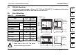
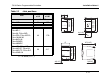
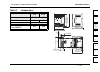
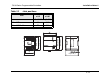
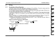
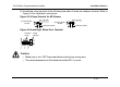
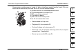
Table Of Contents
- Front Cover
- Manual Number
- Guidelines for the safety
- Marine standard
- Note Concerning the CE Marking
- EMC
- LVD
- Associated Manuals
- Table of Contents
- 1. Introduction
- 2. Terminal layouts
- 3. Installation Notes
- 4. Power Supply
- 5. Inputs
- 6. Outputs
- 7. Diagnostics
- 8. Appendix
- Back Cover
FX1N Series Programmable Controllers Installation Notes 3.
3-19
1
2
3
4
5
6
7
8
Always make sure the power is turned off, before installing a special function board. Only one
board can be used at any one time, do not try to stack multiple boards.
A) Special function or optional equipment board.
B) Optional equipment connector port.
C) M3 screw to secure board.
D) Top cover for board.
E) M3 screw to secure top cover.
Note: Do not remove this screw.
• Remove base unit top cover.
• Plug board A) into connector B).
• Fix board to base unit using screws C).
• Attach top cover for board D) removing section D)’ to expose
connector etc. (if applicable)
• Secure top cover with M3 screw E).