
Hardware Manual
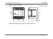
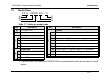
Table Of Contents
- Front Cover
- Manual Number
- Guidelines for the safety
- Marine standard
- Note Concerning the CE Marking
- EMC
- LVD
- Associated Manuals
- Table of Contents
- 1. Introduction
- 2. Terminal layouts
- 3. Installation Notes
- 4. Power Supply
- 5. Inputs
- 6. Outputs
- 7. Diagnostics
- 8. Appendix
- Back Cover
FX1N Series Programmable Controllers Introduction 1.
1-2
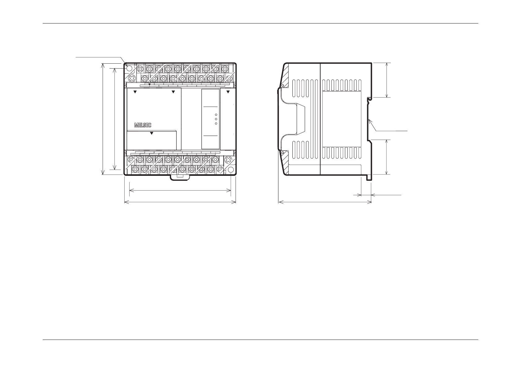
Figure 1.1 :Main unit outline
Please see the previous page for each units width measurement.
N
X14
24V
Y7
Y6
Y0
FX
1N
-24MR
X0 X2
X1
X3 X5
X4
X7
X6
X11
X10
S/S
X1
X12
X15
L
0V
Y11
COM2
COM4
Y10Y5
Y4
Y2
Y1
COM0 COM1
COM3
Y3
POWER
ERROR
IN
OUT
0123
0123
RUN
4567
4567
1110
131110 12
14 15
W
W - 8 (0.32'')
82 (3.23'')
90 (3.55'')
75 (2.96'')
8 (0.32'')
DIN rail
mounting
slot
2 - φ4.5 (0.17'')
27.3(1.08")
27.3(1.08")
UNITS: mm (inches)