
Hardware Manual
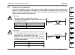
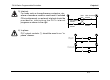
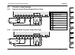
Table Of Contents
- Front Cover
- Manual Number
- Guidelines for the safety
- Marine standard
- Note Concerning the CE Marking
- EMC
- LVD
- Associated Manuals
- Table of Contents
- 1. Introduction
- 2. Terminal layouts
- 3. Installation Notes
- 4. Power Supply
- 5. Inputs
- 6. Outputs
- 7. Diagnostics
- 8. Appendix
- Back Cover
FX1N Series Programmable Controllers Outputs 6.
6-7
1
2
3
4
5
6
7
8
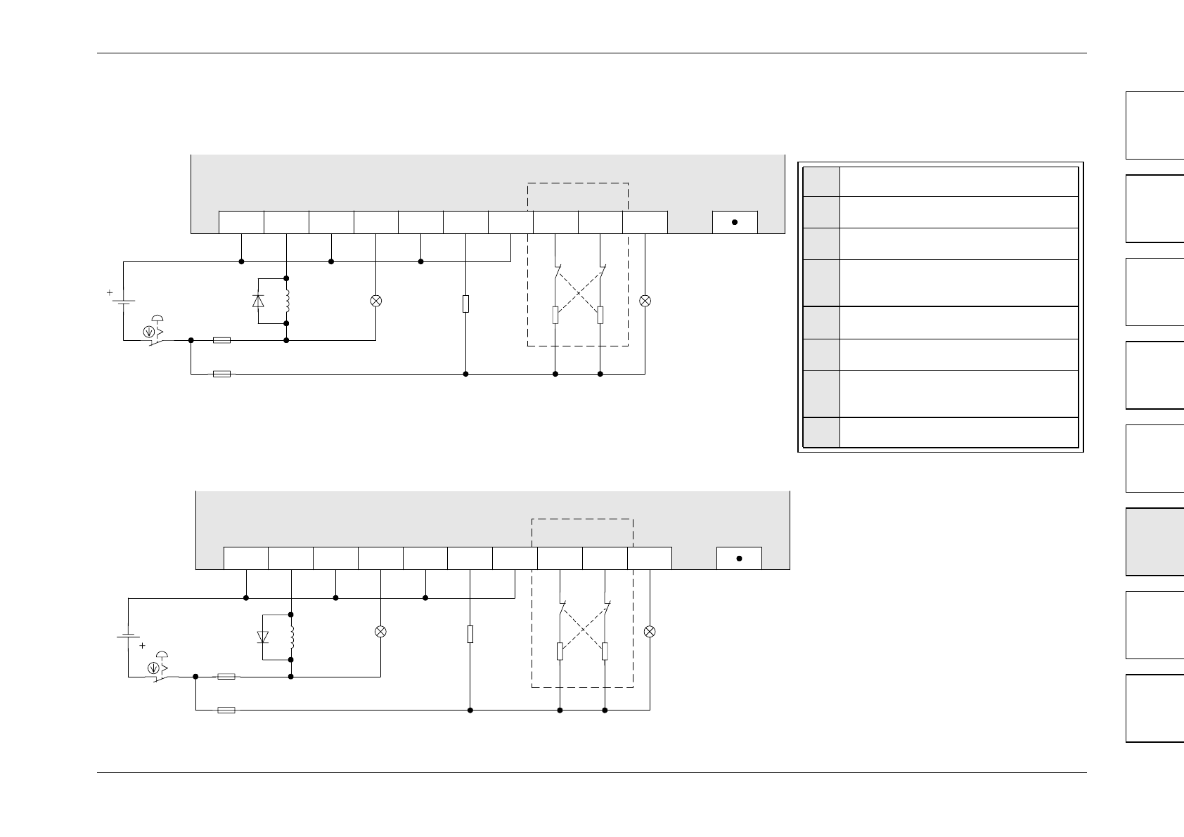
6.3 Transistor Output Example
6.3.1 Transistor Output Writing Diagram (Source Type)
6.3.2 Japanese Model Transistor Output (SInk Type)
➊
Do not use this terminal
➋
Emergency Stop
➌
Fuse
➍
External Mechanical
Interlock (See Section 6.4)
➎
DC Power Supply
➏
Incandescent Lamp
➐
Reverse-current protection
diode
➑
Inductive load
+V0 Y000 Y001 Y003+V1 Y002 Y004
➍
➎
➌
➌
➋
MC1 MC2
MC2 MC1
➑➐ ➏
➏
➊
+V2 +V3 Y005
COM0
Y000 Y001 Y003
COM1 Y002
Y004
➊
➍
➎
➌
➌
➋
MC1 MC2
MC2 MC1
➏➏
➑➐
COM2 COM3
Y005