General-Purpose AC Servo J2-Super Series Program Compatible MODEL 301) MEE Printed in Japan This Instruction Manual uses recycled paper. Specifications subject to change without notice.
Safety Instructions (Always read these instructions before using the equipment.) Do not attempt to install, operate, maintain or inspect the servo amplifier and servo motor until you have read through this Instruction Manual, Installation guide, Servo motor Instruction Manual and appended documents carefully and can use the equipment correctly. Do not use the servo amplifier and servo motor until you have a full knowledge of the equipment, safety information and instructions.
1. To prevent electric shock, note the following: WARNING Before wiring or inspection, switch power off and wait for more than 10 minutes. Then, confirm the voltage is safe with voltage tester. Otherwise, you may get an electric shock. Connect the servo amplifier and servo motor to ground. Any person who is involved in wiring and inspection should be fully competent to do the work. Do not attempt to wire the servo amplifier and servo motor until they have been installed.
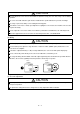
. Additional instructions The following instructions should also be fully noted. Incorrect handling may cause a fault, injury, electric shock, etc. (1) Transportation and installation CAUTION Transport the products correctly according to their weights. Stacking in excess of the specified number of products is not allowed. Do not carry the servo motor by the cables, shaft or encoder. Do not hold the front cover to transport the controller. The controller may drop.
CAUTION Securely attach the servo motor to the machine. If attach insecurely, the servo motor may come off during operation. The servo motor with reduction gear must be installed in the specified direction to prevent oil leakage. For safety of personnel, always cover rotating and moving parts. Never hit the servo motor or shaft, especially when coupling the servo motor to the machine. The encoder may become faulty. Do not subject the servo motor shaft to more than the permissible load.
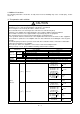
(4) Usage CAUTION Provide an external emergency stop circuit to ensure that operation can be stopped and power switched off immediately. Any person who is involved in disassembly and repair should be fully competent to do the work. Before resetting an alarm, make sure that the run signal is off to prevent an accident. A sudden restart is made if an alarm is reset with the run signal on. Do not modify the equipment. Use a noise filter, etc.
(6) Maintenance, inspection and parts replacement CAUTION With age, the electrolytic capacitor will deteriorate. To prevent a secondary accident due to a fault, it is recommended to replace the electrolytic capacitor every 10 years when used in general environment. Please consult our sales representative. (7) General instruction To illustrate details, the equipment in the diagrams of this Specifications and Instruction Manual may have been drawn without covers and safety guards.
COMPLIANCE WITH EC DIRECTIVES 1. WHAT ARE EC DIRECTIVES? The EC directives were issued to standardize the regulations of the EU countries and ensure smooth distribution of safety-guaranteed products.
(4) Power supply (a) Operate the servo amplifier to meet the requirements of the overvoltage category II set forth in IEC664. For this purpose, a reinforced insulating transformer conforming to the IEC or EN Standard should be used in the power input section. (b) When supplying interface power from external, use a 24VDC power supply which has been insulation-reinforced in I/O.
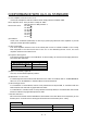
CONFORMANCE WITH UL/C-UL STANDARD (1) Servo amplifiers and servo motors used Use the servo amplifiers and servo motors which comply with the standard model. Servo amplifier series :MR-J2S-10CL to MR-J2S-700CL MR-J2S-10CL1 to MR-J2S-40CL1 Servo motor series :HC-KFS HC-MFS HC-SFS HC-RFS HC-UFS HA-LFS HC-LFS (2) Installation Install a fan of 100CFM (2.8m3/min) air flow 4 [in] (10.16 [cm]) above the servo amplifier or provide cooling of at least equivalent capability.
MEMO A - 10
CONTENTS 1. FUNCTIONS AND CONFIGURATION 1- 1 to 1-24 1.1 Introduction.............................................................................................................................................. 1- 1 1.1.1 Function block diagram.................................................................................................................... 1- 2 1.1.2 System configuration....................................................................................................................
3.9 Servo motor with electromagnetic brake ............................................................................................. 3-31 3.10 Grounding ............................................................................................................................................. 3-34 3.11 Servo amplifier terminal block (TE2) wiring method ....................................................................... 3-35 3.12 Instructions for the 3M connector.....................................
5.2.6 Alarm history clear.......................................................................................................................... 5-25 5.2.7 Software limit................................................................................................................................... 5-25 6. SERVO CONFIGURATION SOFTWARE 6- 1 to 6-24 6.1 Specifications ........................................................................................................................................
8. GENERAL GAIN ADJUSTMENT 8- 1 to 8-12 8.1 Different adjustment methods ............................................................................................................... 8- 1 8.1.1 Adjustment on a single servo amplifier.......................................................................................... 8- 1 8.1.2 Adjustment using servo configuration software............................................................................ 8- 2 8.2 Auto tuning ...............................
13. CHARACTERISTICS 13- 1 to 13- 8 13.1 Overload protection characteristics ................................................................................................... 13- 1 13.2 Power supply equipment capacity and generated loss .................................................................... 13- 2 13.3 Dynamic brake characteristics........................................................................................................... 13- 4 13.4 Encoder cable flexing life .................
15.11 Command and data No. list............................................................................................................. 15-11 15.11.1 Read commands ......................................................................................................................... 15-11 15.11.2 Write commands ........................................................................................................................ 15-14 15.12 Detailed explanations of commands..........................
Optional Servo Motor Instruction Manual CONTENTS The rough table of contents of the optional MELSERVO Servo Motor Instruction Manual is introduced here for your reference. Note that the contents of the Servo Motor Instruction Manual are not included in the Servo Amplifier Instruction Manual. 1. INTRODUCTION 2. INSTALLATION 3. CONNECTORS USED FOR SERVO MOTOR WIRING 4. INSPECTION 5. SPECIFICATIONS 6. CHARACTERISTICS 7. OUTLINE DIMENSION DRAWINGS 8.
MEMO 8
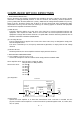
1. FUNCTIONS AND CONFIGURATION 1. FUNCTIONS AND CONFIGURATION 1.1 Introduction The MR-J2S-CL program-compatible AC servo amplifier is based on the MR-J2S-CP AC servo amplifier with built-in positioning functions and incorporates program-driven, single-axis positioning functions. These functions perform positioning operation by creating the position data (target positions), servo motor speeds, acceleration and deceleration time constants, etc. as a program and executing the program.
1. FUNCTIONS AND CONFIGURATION 1.1.1 Function block diagram The function block diagram of this servo is shown below.
1. FUNCTIONS AND CONFIGURATION 1.1.2 System configuration This section describes operations using this servo. You can arrange any configurations from a single-axis to max. 32-axis systems. Further, the connector pins in the interface section allow you to assign the optimum signals to respective systems. (Refer to Sections 1.1.3 and 3.3.3.) The Servo configuration Software (refer to Chapter 6) and personal computer are required to change or assign devices.
1. FUNCTIONS AND CONFIGURATION (2) Operation using external input signals and communication (a) Description Communication can be used to Selection of the program, change parameter values, and confirm monitor data, for example. Enter a forward rotation start (ST1) or reverse rotation start (ST2) through the external I/O. Use this system when position data/speed setting or the host personal computer or the like is used to change the parameter values, for example.
1. FUNCTIONS AND CONFIGURATION 2) Several (up to 32) servo amplifiers are connected with the personal computer by RS-422. Use parameter No. 16 to change the communication system.
1. FUNCTIONS AND CONFIGURATION (3) Operation using communication (a) Description Analog input, forced stop (EMG) and other signals are controlled by external I/O signals and the other devices controlled through communication. Also, you can set each program, selection of the program, and change or set parameter values, for example. Up to 32 axes may be controlled. (b) Configuration 1) One servo amplifier is connected with the personal computer by RS-232C.
1. FUNCTIONS AND CONFIGURATION 2) Several (up to 32) servo amplifiers are connected with the personal computer by RS-422. Use parameter No. 16 to change the communication system.
1. FUNCTIONS AND CONFIGURATION 1.1.3 I/O devices This servo amplifier allows devices to be allocated to the pins of connector CN1A/CN1B as desired. The following devices can be allocated. For device details, refer to Section 3.3.2.
1. FUNCTIONS AND CONFIGURATION 1.
1. FUNCTIONS AND CONFIGURATION Servo amplifier 10CL MR-J2S- 20CL 40CL 60CL 70CL 100CL 200CL 350CL 500CL 700CL 10CL1 20CL1 40CL1 Item Operation mode Home position ignorance (Servo-on position as home position) Manual home position return mode Dog type rear end reference Count type front end reference Dog cradle type Position where servo-on (SON) is switched on is defined as home position. Home position address may be set.
1. FUNCTIONS AND CONFIGURATION 1.3 Function list The following table lists the functions of this servo. For details of the functions, refer to the reference field. Function Description Reference Positioning by program operation Operation is performed in accordance with the contents of any program selected from among pre-created 16 programs. Use the external input signal or communication function to choose the program. Section 4.
1. FUNCTIONS AND CONFIGURATION Function Description Reference Analog monitor The servo status is output in terms of voltage in real time. Section 5.2.4 Alarm history By using the Servo configuration Software, the current alarm and five past alarm numbers are stored and displayed. Section 6.8 I/O signal selection (Device setting) By using the Servo configuration Software, any devices can be assigned to 9 input, 5 output and 1 I/O pins. Section 6.6 Torque limit Servo motor-torque is limited.
1. FUNCTIONS AND CONFIGURATION (2) Model MR–J2S– CL MR–J2S–100CL or less Series MR–J2S–200CL 350CL Power Supply Symbol Power supply None 3-phase 200 to 230VAC (Note2) 1-phase 230VAC (Note1) 1-phase 100V to 120VAC 1 Rating plate Note:1. Not supplied to the servo amplifier of MR-J2S-60CL or more. 2. Not supplied to the servo amplifier of MR-J2S-100CL or more.
1. FUNCTIONS AND CONFIGURATION 1.6 Structure 1.6.1 Part names (1) MR-J2S-100CL or less Name/Application Reference Battery holder Contains the battery for absolute position data backup. Section4.5 Battery connector (CON1) Used to connect the battery for absolute position data backup. Section4.5 Display The 5-digit, seven-segment LED shows the servo status and alarm number. Chapter7 Operation section Used to perform status display, diagnostic, alarm and parameter setting operations.
1. FUNCTIONS AND CONFIGURATION (2) MR-J2S-200CL MR-J2S-350CL POINT This servo amplifier is shown without the front cover. For removal of the front cover, refer to Section 1.6.2. MODE UP DOWN SET Name/Application Reference Battery holder Contains the battery for absolute position data backup. Section4.5 Battery connector (CON1) Used to connect the battery for absolute position data backup. Section4.5 Display The 5-digit, seven-segment LED shows the servo status and alarm number.
1. FUNCTIONS AND CONFIGURATION (3) MR-J2S-500CL POINT The servo amplifier is shown without the front cover. For removal of the front cover, refer to Section 1.6.2. Name/Application Battery connector (CON1) Used to connect the battery for absolute position data backup. Battery holder Contains the battery for absolute position data backup. Display The 5-digit, seven-segment LED shows the servo status and alarm number. MODE UP DOWN Reference Section4.5 Section4.
1. FUNCTIONS AND CONFIGURATION (4) MR-J2S-700CL POINT The servo amplifier is shown without the front cover. For removal of the front cover, refer to next page. Name/Application MODE UP DOWN SET Reference Battery connector (CON1) Used to connect the battery for absolute position data backup. Section4.5 Battery holder Contains the battery for absolute position data backup. Section4.5 Display The 5-digit, seven-segment LED shows the servo status and alarm number.
1. FUNCTIONS AND CONFIGURATION 1.6.2 Removal and reinstallation of the front cover To avoid the risk of an electric shock, do not open the front cover while power is on. CAUTION (1) For MR-J2S-200CL or more Reinstallation of the front cover Removal of the front cover 1) Front cover hook (2 places) 2) 2) Front cover 1) Front cover socket (2 places) 1) Hold down the removing knob. 2) Pull the front cover toward you. 1) Insert the front cover hooks into the front cover sockets of the servo amplifier.
1. FUNCTIONS AND CONFIGURATION (3) For MR-J2S-700CL Reinstallation of the front cover Removal of the front cover Front cover hook (2 places) A) B) 2) 2) 1) A) 1) Front cover socket (2 places) 1) Push the removing knob A) or B), and put you finger into the front hole of the front cover. 2) Pull the front cover toward you. 1) Insert the two front cover hooks at the bottom into the sockets of the servo amplifier. 2) Press the front cover against the servo amplifier until the removing knob clicks.
1. FUNCTIONS AND CONFIGURATION 1.7 Servo system with auxiliary equipment WARNING To prevent an electric shock, always connect the protective earth (PE) terminal (terminal marked ) of the servo amplifier to the protective earth (PE) of the control box.
1. FUNCTIONS AND CONFIGURATION (b) For 1-phase 100V to 120VAC 1-phase 100V to 120VAC power supply Options and auxiliary equipment Options and auxiliary equipment Reference No-fuse breaker Section 14.2.2 Cables Section 14.2.1 Magnetic contactor Section 14.2.2 Manual pulse generator Section 14.1.8 Chapter 6 External digital display Section 14.1.7 Servo configuration software Regenerative brake option No-fuse breaker (NFB) or fuse Reference Section 14.1.
1. FUNCTIONS AND CONFIGURATION (2) MR-J2S-200CL MR-J2S-350CL 3-phase 200V to 230VAC power supply Options and auxiliary equipment Reference No-fuse breaker Section 14.2.2 Cables Section 14.2.1 Magnetic contactor Section 14.2.2 Manual pulse generator Section 14.1.8 Chapter 6 External digital display Section 14.1.7 Servo configuration software No-fuse breaker (NFB) or fuse Options and auxiliary equipment Reference Regenerative brake option Power factor improving reactor Section 14.2.
1. FUNCTIONS AND CONFIGURATION (3) MR-J2S-500CL 3-phase 200V to 230VAC power supply Options and auxiliary equipment No-fuse breaker (NFB) or fuse Reference Options and auxiliary equipment Reference No-fuse breaker Section 14.2.2 Cables Section 14.2.1 Magnetic contactor Section 14.2.2 Manual pulse generator Section 14.1.8 Chapter 6 External digital display Section 14.1.7 Servo configuration software Regenerative brake option Section 14.1.1 Power factor improving reactor Section 14.2.
1. FUNCTIONS AND CONFIGURATION (4) MR-J2S-700CL Options and auxiliary equipment 3-phase 200V to 230VAC power supply Reference Options and auxiliary equipment Reference No-fuse breaker Section 14.2.2 Cables Section 14.2.1 Magnetic contactor Section 14.2.2 Manual pulse generator Section 14.1.8 Chapter 6 External digital display Section 14.1.7 Servo configuration software Regenerative brake option Section 14.1.1 Power factor improving reactor Section 14.2.
2. INSTALLATION 2. INSTALLATION CAUTION Stacking in excess of the limited number of products is not allowed. Install the equipment to incombustibles. Installing them directly or close to combustibles will led to a fire. Install the equipment in a load-bearing place in accordance with this Instruction Manual. Do not get on or put heavy load on the equipment to prevent injury. Use the equipment within the specified environmental condition range.
2. INSTALLATION 2.2 Installation direction and clearances CAUTION Do not hold the front cover to transport the controller. The controller may drop. The equipment must be installed in the specified direction. Otherwise, a fault may occur. Leave specified clearances between the servo amplifier and control box inside walls or other equipment. (1) Installation of one servo amplifier Control box Control box 40mm (1.6 in.) or more Servo amplifier Wiring clearance 70mm (2.8 in.) Up 10mm (0.4 in.
2. INSTALLATION (2) Installation of two or more servo amplifiers Leave a large clearance between the top of the servo amplifier and the internal surface of the control box, and install a fan to prevent the internal temperature of the control box from exceeding the environmental conditions. Control box 10mm (0.4 in.) or more 100mm (4.0 in.) or more 30mm (1.2 in.) or more 30mm (1.2 in.) or more 40mm (1.6 in.
2. INSTALLATION 2.4 Cable stress (1) The way of clamping the cable must be fully examined so that flexing stress and cable's own weight stress are not applied to the cable connection. (2) For use in any application where the servo motor moves, fix the cables (encoder, power supply, brake) supplied with the servo motor, and flex the optional encoder cable or the power supply and brake wiring cables. Use the optional encoder cable within the flexing life range.
3. SIGNALS AND WIRING 3. SIGNALS AND WIRING WARNING Any person who is involved in wiring should be fully competent to do the work. Before starting wiring, switch power off, then wait for more than 10 minutes, and after the charge lamp has gone off, make sure that the voltage is safe in the tester or like. Otherwise, you may get an electric shock. Ground the servo amplifier and the servo motor securely. Do not attempt to wire the servo amplifier and servo motor until they have been installed.
3. SIGNALS AND WIRING 3.1 Standard connection example Servo amplifier Proximity dog (Note 3, 7) (Note 3, 7) CN1A CN1A DOG 8 9 COM Servo-on SON 19 SG 10 18 Home position return completion (Note 2, 4) ZP RA5 10m (32.79ft.) or less (Note 5) Forward rotation stroke end (Note 3, 7) (Note 3, 7) CN1B CN1B LSP 16 3 VDD Reverse rotation stroke end LSN 17 Program input 1 PI1 8 Program input 2 PI2 9 Forward rotation start ST1 Program No.
3. SIGNALS AND WIRING Note: 1. To prevent an electric shock, always connect the protective earth (PE) terminal of the servo amplifier to the protective earth (PE) of the control box. 2. Connect the diode in the correct direction. If it is connected reversely, the servo amplifier will be faulty and will not output signals, disabling the emergency stop and other protective circuits. 3. CN1A, CN1B, CN2 and CN3 have the same shape. Wrong connection of the connectors will lead to a fault. 4.
3. SIGNALS AND WIRING 3.2 Internal connection diagram of servo amplifier This section gives the internal connection diagram where the signal assignment is in the initial status. Servo amplifier CN1B VDD 3 COM 13 24VDC CN1A CN1A COM 18 9 ZP Approx. 4.7k DOG 8 SON 19 SG 10, 20 Approx. 4.7k CN1B CN1B DI0 5 4 OUT1 6 PED 18 ALM 19 RD Approx. 4.7k ST1 7 Approx. 4.7k PI1 8 Approx. 4.
3. SIGNALS AND WIRING 3.3 I/O signals 3.3.1 Connectors and signal arrangements POINT The connector pin-outs shown above are viewed from the cable connector wiring section side.
3. SIGNALS AND WIRING 3.3.2 Signal (devices) explanations (1) I/O devices POINT The devices not indicated in the Connector Pin No. field of the I/O devices can be assigned to the connector CN1A/CN1B using the Servo Configuration software. In the factory setting state, Forced stop (EMG) and Automatic/manual selection (MD0) are not assigned to the pins but are preset to turn on automatically. (a) Pins whose devices can be changed Refer to Section 3.6.
3. SIGNALS AND WIRING Device name Forward rotation stroke end Devices Connector symbol pin No. LSP Functions/Applications CN1B-16 To start operation, turn LSP/LSN on. Turn it off to bring the motor to a sudden stop and make it servo-locked. Set " 1" in parameter No. 22 to make a slow stop. (Refer to Section 5.2.5.) (Note) Input signals LSP Reverse rotation stroke end LSN CN1B-17 LSN 1 1 0 1 1 0 0 0 Operation CCW direction CW direction Note.
3. SIGNALS AND WIRING Device name Devices Connector symbol pin No. Functions/Applications Program No. selection 1 DI0 CN1B-5 Select the program number from among those combined by DI0, DI1, DI2 and DI3 to start operation on the leading edge of ST1 in the program operation mode. Program No. selection 2 DI1 CN1B-14 Program No. selection 3 DI2 Program No.
3. SIGNALS AND WIRING Device name Temporary stop/Restart Manual pulse generator multiplication 1 Manual pulse generator multiplication 2 Devices Connector Functions/Applications symbol pin No. STP Turn STP on during program operation to make a temporary stop. Turn it on again to make a restart. If any of Program inputs 1 to 3 (PI1 to PI3) is turned on during a temporary stop, it is ignored.
3. SIGNALS AND WIRING (c) Output devices Device name Trouble Ready Movement complete Home position return completion Electromagnetic brake interlock Position range Warning Battery warning Limiting torque Temporary stop Program output 1 Devices Connector Functions/Applications symbol pin No. ALM CN1B-18 ALM turns off when power is switched off or the protective circuit is activated to shut off the base circuit. Without alarm occurring, ALM turns on within 1s after power-on.
3. SIGNALS AND WIRING (2) Input signal For the input interfaces (symbols in I/O column in the table), refer to Section 3.6.2. Signal Manual pulse generator Override Analog torque limit Signal symbol PP PG Connector pin No. I/O division CN1A-3 Used to connect the manual pulse generator (MR-HDP01). CN1A-13 For details, refer to Section 14.1.8. NP CN1A-2 NG CN1A-12 VC CN1B-2 TLA Functions/Applications 10 to 10V is applied to across VC-LG to limit the servo motor speed.
3. SIGNALS AND WIRING (4) Communication POINT Refer to Chapter 15 for the communication function. Signal Signal symbol Connector pin No. Functions/Applications RS-422 I/F SDP SDN RDP RDN CN3-9 RS-422 and RS-232C functions cannot be used together. CN3-19 Choose either one in parameter No. 16. CN3-5 CN3-15 RS-422 termination TRE CN3-10 Termination resistor connection terminal of RS-422 interface. When the servo amplifier is the termination axis, connect this terminal to RDN (CN3-15).
3. SIGNALS AND WIRING 3.4 Detailed description of signals (devices) 3.4.1 Forward rotation start Reverse rotation start Temporary stop/Restart (1) A forward rotation start (ST1) or a reverse rotation start (ST2) should make the sequence which can be used after the main circuit has been established. These signals are invalid if it is switched on before the main circuit is established. Normally, it is interlocked with the ready signal (RD).
3. SIGNALS AND WIRING 3.4.2 Movement complete POINT If servo-on occurs after a stop made by servo-off, alarm occurrence or Forced stop (EMG) ON during automatic operation, Movement complete (PED), turn on. To make a start again, confirm the program No. being specified, and turn on Forward rotation start (ST1). The following timing charts show the output timing relationships between the position command generated in the servo amplifier and the Movement complete (PED).
3. SIGNALS AND WIRING 3.4.3 Override POINT When using the override (VC), make the override selection (OVR) device available. The override (VC) may be used to change the servo motor speed. The following table lists the signals and parameter related to the override: Item Name Analog input signal Override (VC) Contact input signal Override selection (OVR) Parameter No.25 override offset Remarks Servo Configuration Software setting required.
3. SIGNALS AND WIRING 3.4.4 Torque limit POINT To use the torque limit, make the external torque limit selection (TL) and internal torque limit selection (TL2) available. The following table lists the signals and parameters related to the torque limit: Item Name Analog input signal Remarks Analog torque limit (TLA) External torque limit selection (TL) Internal torque limit selection (TL2) Limiting torque (TLC) No.28 (internal torque limit 1) No.29 (internal torque limit 2) No.
3. SIGNALS AND WIRING (3) External torque limit selection (TL), internal torque limit selection (TL2) To use the external torque limit selection (TL) and internal torque limit selection (TL2), make them available using the Servo Configuration Software (refer to Chapter 6). These input signals may be used to choose the torque limit values made valid. (Note) External input signals TL2 TL 0 0 0 1 1 0 1 1 Torque limit value made valid Internal torque limit value 1 (parameter No. 28) TLA Parameter No.
3. SIGNALS AND WIRING 3.5 Alarm occurrence timing chart CAUTION When an alarm has occurred, remove its cause, make sure that the operation signal is not being input, ensure safety, and reset the alarm before restarting operation. When an alarm occurs in the servo amplifier, the base circuit is shut off and the servo motor is coated to a stop. Switch off the main circuit power supply in the external sequence.
3. SIGNALS AND WIRING 3.6 Interfaces 3.6.1 Common line The following diagram shows the power supply and its common line. CN1A CN1B CN1A CN1B 24VDC VDD ALM,etc COM DO-1 SON,etc. Dl-1 RA SG OPC Manual pulse generator MR-HDP01 5V PP(NP) A(B) SG 0V SG 5V OP LG 15VDC 10% 30mA P15R LA,etc Differential line driver output 35mA or less LAR,etc LG SD TLA VC, etc. Analog input ( 10V/max.
3. SIGNALS AND WIRING 3.6.2 Detailed description of the interfaces This section gives the details of the I/O signal interfaces (refer to I/O Division in the table) indicated in Sections 3.3.2. Refer to this section and connect the interfaces with the external equipment. (1) Digital input interface DI-1 Give a signal with a relay or open collector transistor. Source input is also possible. Refer to (6) in this section.
3. SIGNALS AND WIRING (b) Lamp load For use of internal power supply For use of external power supply Servo amplifier 24VDC Servo amplifier VDD 24VDC Do not connect VDD-COM. VDD COM COM R R ALM, etc. 24VDC 10% ALM, etc. SG SG (3) Encoder pulse output DO-2 (a) Open collector system Interface Max. output current : 35mA Servo amplifier Servo amplifier OP OP LG LG SD SD 5 to 24VDC Photocoupler (b) Differential line driver system 1) Interface Max.
3. SIGNALS AND WIRING (4) Analog input Input impedance 10 to 12k Servo amplifier 15VDC P15R Upper limit setting 2k VC‚ etc 2k LG Approx. 10k SD (5) Analog output Output voltage 10V Max.1mA Max. output current Resolution : 10bits Servo amplifier MO1 (MO2) LG 10k Reading in one or A both directions 1mA meter SD (6) Source input interface When using the input interface of source type, all Dl-1 input signals are of source type. Source output cannot be provided.
3. SIGNALS AND WIRING 3.7 Input power supply circuit CAUTION When the servo amplifier has become faulty, switch power off on the servo amplifier power side. Continuous flow of a large current may cause a fire. Use the trouble signal to switch power off. Otherwise, a regenerative brake transistor fault or the like may overheat the regenerative brake resistor, causing a fire. 3.7.
3. SIGNALS AND WIRING (2) For 1-phase 100 to 120VAC or 1-phase 230VAC power supply Forced RA stop OFF ON MC MC SK Power supply 1-phase 100 to 120VAC or 1-phase 230VAC NFB MC L1 Servo amplifier L2 L3 (Note) L11 L21 EMG Forced stop Servo-on SON SG VDD COM ALM Note : Not provided for 1-phase 100 to 120VAC.
3. SIGNALS AND WIRING 3.7.2 Terminals The positions and signal arrangements of the terminal blocks change with the capacity of the servo amplifier. Refer to Section 12.1. Symbol Connection Target (Application) Description Supply L1, L2 and L3 with the following power: For 1-phase 230VAC, connect the power supply to L1/L2 and leave L3 open.
3. SIGNALS AND WIRING 3.7.3 Power-on sequence (1) Power-on procedure 1) Always wire the power supply as shown in above Section 3.7.1 using the magnetic contactor with the main circuit power supply (three-phase 200V: L1, L2, L3, single-phase 230V: L1, L2). Configure up an external sequence to switch off the magnetic contactor as soon as an alarm occurs.
3. SIGNALS AND WIRING 3.8 Connection of servo amplifier and servo motor 3.8.1 Connection instructions WARNING Insulate the connections of the power supply terminals to prevent an electric shock. CAUTION Connect the wires to the correct phase terminals (U, V, W) of the servo amplifier and servo motor. Otherwise, the servo motor will operate improperly. Do not connect AC power supply directly to the servo motor. Otherwise, a fault may occur.
3. SIGNALS AND WIRING Servo motor Connection diagram Servo amplifier Servo motor U (Red) U V (White) V W (Green) (Note 1) 24VDC HC-MF053 (B) to 73 (B) HA-FF053 (B) to 63 (B) HC-UF13 (B) to 73 (B) Motor W (Black) (Note3) B1 (Note2) B2 Electromagnetic brake EMG To be shut off when servoon (SON) switches off or by trouble (ALM) CN2 Encoder Encoder cable Note:1.
3. SIGNALS AND WIRING 3.8.3 I/O terminals (1) HC-KFS HC-MFS HC-UFS3000r/min series Encoder connector signal arrangement Power supply lead 4-AWG19 0.3m (0.98ft.) a Encoder cable 0.3m (0.98ft.
3. SIGNALS AND WIRING (2) HC-SFS HC-RFS HC-UFS2000 r/min series Servo motor side connectors Servo motor For power supply For encoder HC-SFS81(B) HC-SFS121(B) to 301(B) 10PD-B 353(B) HC-RFS103(B) to 203 (B) Encoder connector HC-RFS353(B) b Brake connector c 4P 17PD-B MS3102A20- CE05-2A22- 29P 23PD-B The connector CE05-2A24- 503(B) HC-UFS72(B) Power supply connector MS3102A10SL- CE05-2A32- HC-SFS702(B) a shared.
3. SIGNALS AND WIRING 3.9 Servo motor with electromagnetic brake Configure the electromagnetic brake operation circuit so that it is activated not only by the servo amplifier signals but also by an external forced stop (EMG). Contacts must be open when servo-on (SON) is off or when a trouble (ALM) is present and when an electromagnetic brake interlock (MBR). Circuit must be opened during forced stop (EMG).
3. SIGNALS AND WIRING (3) Timing charts (a) Servo-on (SON) command (from controller) ON/OFF Tb (ms) after servo-on (SON) is switched off, servo lock is released and the servo motor coasts. If the electromagnetic brake is made valid in the servo lock status, the brake life may be shorter. For use in vertical lift and similar applications, therefore, set delay time (Tb) to the time which is about equal to the electromagnetic brake operation delay time and during which the load will not drop.
3.
3. SIGNALS AND WIRING 3.10 Grounding Ground the servo amplifier and servo motor securely. To prevent an electric shock, always connect the protective earth (PE) terminal of the servo amplifier with the protective earth (PE) of the control box. WARNING The servo amplifier switches the power transistor on-off to supply power to the servo motor. Depending on the wiring and ground cablerouting, the servo amplifier may be affected by the switching noise (due to di/dt and dv/dt) of the transistor.
3. SIGNALS AND WIRING 3.11 Servo amplifier terminal block (TE2) wiring method 1) Termination of the cables Solid wire: After the sheath has been stripped, the cable can be used as it is. (Cable size: 0.2 to 2.5mm2) Approx. 10mm (0.39inch) Twisted wire: Use the cable after stripping the sheath and twisting the core. At this time, take care to avoid a short caused by the loose wires of the core and the adjacent pole. Do not solder the core as it may cause a contact fault. (Cable size: 0.2 to 2.
3. SIGNALS AND WIRING Use of a flat-blade torque screwdriver is recommended to manage the screw tightening torque. The following table indicates the recommended products of the torque screwdriver for tightening torque management and the flat-blade bit for torque screwdriver. When managing torque with a Phillips bit, please consult us. Product Torque screwdriver Bit for torque screwdriver Model N6L TDK B-30, flat-blade, H3.5 X 73L Maker/Representative Nakamura Seisakusho Shiro Sangyo 3.
4. OPERATION 4. OPERATION 4.1 When switching power on for the first time 4.1.1 Pre-operation checks Before starting operation, check the following: (1) Wiring (a) A correct power supply is connected to the power input terminals (L1, L2, L3, L11, L21) of the servo amplifier. (b) The servo motor power supply terminals (U, V, W) of the servo amplifier match in phase with the power input terminals (U, V, W) of the servo motor.
4. OPERATION 4.1.2 Startup WARNING Do not operate the switches with wet hands. You may get an electric shock. CAUTION Before starting operation, check the parameters. Some machines may perform unexpected operation. During power-on or soon after power-off, do not touch the servo amplifier heat sink, regenerative brake resistor, servo motor, etc. as they may be at high temperatures. You may get burnt. Connect the servo motor with a machine after confirming that the servo motor operates properly alone.
4. OPERATION (2) Startup procedure (a) Power on 1) Switch off the servo-on (SON). 2) When main circuit power/control circuit power is switched on, "PoS" (Current position) appears on the servo amplifier display. In the absolute position detection system, first power-on results in the absolute position lost (AL.25) alarm and the servo system cannot be switched on. This is not a failure and takes place due to the uncharged capacitor in the encoder.
4. OPERATION (f) Home position return Perform home position return as required. Refer to Section 4.4 for home position return types. A parameter setting example for dog type home position return is given here. Parameter Name Setting Description 000 Dog type home position return is selected. Home position return is started in address incremented direction. Proximity dog (DOG) is valid at OFF. No.8 Home position return type No.9 No.10 No.
4. OPERATION 4.2 Program operation mode 4.2.1 What is program operation mode? Make selection with the input signals or by communication from among the programs that have been created in advance using the Servo Configuration software, and perform operation with Forward rotation start (ST1). This servo is factory-set to the absolute position command system.
4. OPERATION 4.2.2 Programming language The maximum number of program steps is 120. Though up to 16 programs can be created, the total number of program steps is up to 120. The set program can be selected using Program No. selection 1 (DI0) to Program No. selection 4 (ID3).
4. OPERATION Command Name MOVIA Incremental continuous move command SYNC (Note 1) Waiting external signal to switch on OUTON (Note 1 3) External signal ON output Setting Setting range MOVIA -999999 (Set value) to 999999 SYNC (Set value) OUTON (Set value) Indirect Addressing Unit 10STM m Description The set value is regarded as an incremental value for movement. Always use this command with the "MOVI" command.
4. OPERATION Command COUNT (Note 1) Name Setting External COUNT -999999 pulse counter (Set value) to 999999 FOR NEXT Step repeat command FOR (SET value) NEXT LPOS (Note 1) Position latch LPOS TIM ZRT Setting range Dwell command time Zeroing 0, 1 to 10000 TIM 1 to 2000 (Set value) Unit Indirect Addressing Executes the next step when the pulse counter value becomes greater than the count value set to the "COUNT" command. COUNT (0) is clearing of the pulse counter.
4. OPERATION (2) Details of programming languages (a) Details of the command (SPN STA STB STC STD) "SPN" "STA" "STB" "STC" and "STD" commands will be validated, when the "MOV" and "MOVA" commands are executing. The setting numbers will be validated, expect resetting the numbers. 1) Program example 1 When operation is to be performed in two patterns that have the same servo motor speed, acceleration time constant and deceleration time constant but different move commands.
4. OPERATION 2) Program example 2 When operation is to be performed in two patterns that have different servo motor speeds, acceleration time constants, deceleration time constants and move commands.
4. OPERATION (b) Continuous move command (MOVA MOVIA) POINT "MOV" cannot be used with "MOVIA", and "MOVI" cannot be used with "MOVA". The "MOVA" command is a continuous move command for the "MOV" command. After execution of the movement by the "MOV" command, the movement of the "MOVA" command can be executed continuously without a stop. The speed changing point of the "MOVA" command is the deceleration starting position of the operation performed by the preceding "MOV" and "MOVA" commands.
4. OPERATION 2) Program example 2 (Wrong usage) In continuous operation, the acceleration or deceleration time constant cannot be changed at each speed change. Hence, the "STA", "STB" or "STD" command is ignored if it is inserted for a speed change.
4. OPERATION 2) Program example 2 Using parameter No. 74 to 76, Program output 1 (OUT1) to Program out 3 (OUT3) can be turned off automatically. Parameter No. Name Setting 74 75 76 OUT1 output time setting OUT2 output time setting OUT3 output time setting 20 10 50 Description OUT1 is turned off in 200ms. OUT2 is turned off in 100ms. OUT3 is turned off in 500ms.
4. OPERATION 3) Program example 3 When the "TRIP" and "TRIPI" commands are used to set the position addresses where the "OUTON" and "OUTOF" commands will be executed. Program Description Speed (Motor speed) Acceleration time constant Deceleration time constant Absolute move command Absolute trip point Program output 2 (OUT 2) is turned ON. Absolute trip point Program output 2 (OUT 2) is turned OFF. Dwell command time Incremental move command Incremental trip point Program output 2 (OUT 2) is turned ON.
4. OPERATION 4) Program example 4 POINT "MOV" cannot be used with "TRIPI". Note that the "TRIP" and "TRIPI" commands do not execute the next step unless the axis passes the preset address or travels the preset moving distance. Program Description Speed (Motor speed) Acceleration time constant Deceleration time constant Incremental move command Absolute trip point Program output 3 (OUT 3) is turned ON.
4. OPERATION (d) Dwell (TIM) To the "TIM (setting value)" command, set the time from when the command remaining distance is "0" until the next step is executed. For reference, the following examples show the operations performed when this command is used with the other commands.
4. OPERATION 3) Program example 3 Program Description Speed (Motor speed) Acceleration/deceleration time constant Incremental move command Program output 1 (OUT 1) is turned ON.
4. OPERATION 5) Program example 5 Program SPN (1000) STC (20) MOVI (1000) TIM (20) SYNC (1) MOVI (500) STOP Description Speed (Motor speed) 1000 [r/min] Acceleration/deceleration time constant 20 [ms] Incremental move command 1000 [ 10STM m] Dwell command time 200 [ms] a) Step is suspended until Program input (PI1) turns ON. Incremental move command 500 [ 10STM m] Program end Forward rotation Servo motor 0r/min speed ON Program input1 (PI1) OFF a) PI1 is accepted in 200ms or later.
4. OPERATION (e) Interrupt positioning command (ITP) POINT When Interrupt positioning (ITP) is used for positioning, a stop position differs depending on the servo motor speed provided when the "ITP" command is enabled. When the "ITP" command is used in a program, the axis stops at the position by the set value farther from the position where any of Program input 1 to 3 (PI1 to PI3) turned ON.
4. OPERATION 2) Program example 2 If the moving distance of the "ITP" command is less than the moving distance necessary for deceleration, the actual deceleration time constant becomes less than the set value of the "STB" command. Program Description Speed (Motor speed) 500 [r/min] Acceleration time constant 200 [ms] Deceleration time constant 300 [ms] Absolute move command 1000 [ 10STM m] Step is suspended until Program input (PI1) turns ON.
4. OPERATION (g) Step repeat command (FOR NEXT) POINT "FOR ... NEXT" cannot be placed within "FOR ... NEXT". The steps located between the "FOR (set value)" command and "NEXT" command is repeated by the preset number of times.
4. OPERATION (h) Program count command (TIMES) By setting the number of times to the "TIMES (setting value)" command placed at the beginning of a program, the program can be executed repeatedly. When the program is to be executed once, the "TIMES (setting value)" command is not necessary. Setting "0" selects endless repetition.
4. OPERATION (i) Position latch (LPOS) POINT When Current position latch input (LPS) is used to store the current position, the value differs depending on the servo motor speed provided when LPS has turned ON. The current position where Current position latch input (LPS) is turned ON is stored. The stored position data can be read by the communication function. (Refer to Section 15.12.12) The current position latch function set in a program is canceled at the end of that program.
4. OPERATION (j) Indirect addressing using general-purpose registers (R1-R4, D1-D4) The set values of the "SPN", "STA", "STB", "STC", "STD", "MOV", "MOVI", "MOVA", "MOVIA", "TIM" and "TIMES" commands can be addressed indirectly. The values stored in the general-purpose registers (R1-R4, D1-D4) are used as the set values of the commands. Change the values of the general-purpose registers using the communication command when the program is not being executed by the communication command.
4. OPERATION 4.2.3 Basic setting of signals and parameters Create programs in advance using the Servo Configuration software. (Refer to Section 4.2.2 and Section 6.5) (1) Parameter (a) Command mode selection (parameter No.0) Make sure that the absolute value command system has been selected as shown below. Parameter No. 0 0 Absolute value command system (initial value) (b) ST1 coordinate system selection (parameter No.
4. OPERATION 4.2.4 Program operation timing chart (1) Operation conditions The timing chart shown below assumes that the following program is executed in the absolute value command system where a home position return is completed. Program No.1 SPN (1000) STC (100) MOV (5000) SYNC (1) STC (50) MOV (7500) STOP Description Speed (Motor speed) 1000 [r/min] Acceleration time constant 100 [ms] Absolute move command 5000 [ 10STM m] Move command 1 Step is suspended until Program input (PI1) turns ON.
4. OPERATION 4.3 Manual operation mode For machine adjustment, home position matching, etc., jog operation or a manual pulse generator may be used to make a motion to any position. 4.3.1 Jog operation (1) Setting Set the input signal and parameters as follows according to the purpose of use. In this case, the program No. selection 1 to 4 (DI0 to DI3) are invalid: Item Setting method Manual operation mode selection Description Automatic/manual selection (MD0) MD0 is switched off.
4.
4. OPERATION 4.3.2 Manual pulse generator operation (1) Setting Set the input signal and parameters as follows according to the purpose of use. In this case, the program No. selection 1 to 4 (DI0 to DI3) are invalid: Item Setting method Manual operation mode selection Description Automatic/manual selection (MD0) MD0 is switched off. Parameter No.1 Set the multiplication ratio of servo motor rotation to the pulses generated by the manual pulse generator.
4. OPERATION (b) Using the input signals for setting Set the pulse generator multiplication 1 (TP0) and pulse generator multiplication 2 (TP1) to the input signals in "Device setting" on the Servo Configuration Software (refer to Chapter 6). Pulse generator multiplication 2 (across TP1) Pulse generator multiplication 1 (across TP0) Multiplication ratio of servo motor rotation to manual pulse generator rotation 0 0 Parameter No.
4. OPERATION 4.4 Manual home position return mode 4.4.1 Outline of home position return Home position return is performed to match the command coordinates with the machine coordinates. In the incremental system, home position return is required every time input power is switched on. In the absolute position detection system, once home position return is done at the time of installation, the current position is retained if power is switched off.
4. OPERATION (2) Home position return parameter When performing home position return, set parameter No.8 as follows: Parameter No.
4. OPERATION 4.4.2 Dog type home position return A home position return method using a proximity dog. With deceleration started at the front end of the proximity dog, the position where the first Z-phase signal is given past the rear end of the dog or a motion has been made over the home position shift distance starting from the Z-phase signal is defined as a home position.
4. OPERATION (3) Timing chart The following shows the timing chart that starts after selection of the program including the "ZRT" command. Movement complete (PED) ON OFF Home position return ON completion (ZP) OFF Parameter No. 41 Acceleration time constant Forward Servo motor speed rotation 0 r/min Parameter No. 41 Home position return speed Parameter No. 9 Deceleration time constant Creep speed Parameter No.
4. OPERATION 4.4.3 Count type home position return In count type home position return, a motion is made over the distance set in parameter No.43 (moving distance after proximity dog) after detection of the proximity dog front end. The position where the first Zphase signal is given after that is defined as a home position. Hence, if the proximity dog (DOG) is 10ms or longer, there is no restriction on the dog length.
4. OPERATION 4.4.4 Data setting type home position return Data setting type home position return is used when it is desired to determine any position as a home position. JOG operation, manual pulse generator operation or like can be used for movement. (1) Signals, parameters Set the input signals and parameters as follows: Item Device/Parameter used Manual home position return mode Automatic/manual selection selection (MD0) Data setting type home position return Parameter No.
4. OPERATION 4.4.5 Stopper type home position return In stopper type home position return, a machine part is pressed against a stopper or the like by jog operation, manual pulse generator operation or the like to make a home position return and that position is defined as a home position.
4. OPERATION 4.4.6 Home position ignorance (servo-on position defined as home position) POINT When a home position-ignored home position return is executed, the program including the "ZRT" command need not be selected. The position where servo is switched on is defined as a home position. (1) Signals, parameter Set the input signals and parameter as follows: Item Home position ignorance Home position return position data Device/Parameter used Parameter No.
4. OPERATION 4.4.7 Dog type rear end reference home position return POINT This home position return method depends on the timing of reading Proximity dog (DOG) that has detected the rear end of a proximity dog. Hence, if a home position return is made at the creep speed of 100r/min, an error of 200 pulses will occur in the home position. The error of the home position is larger as the creep speed is higher.
4. OPERATION 4.4.8 Count type front end reference home position return POINT This home position return method depends on the timing of reading Proximity dog (DOG) that has detected the front end of a proximity dog. Hence, if a home position return is made at the creep speed of 100r/min, an error of 200 pulses will occur in the home position. The error of the home position is larger as the creep speed is higher.
4. OPERATION 4.4.9 Dog cradle type home position return The position where the first Z-phase signal is issued after detection of the proximity dog front end can be defined as a home position. (1) Signals, parameters Set the input signals and parameters as indicated below. Item Device/Parameter used Manual home position return mode selection Dog cradle type home position return Description Automatic/manual selection (MD0) MD0 is switched on. 7: Select the dog cradle type. Parameter No.
4. OPERATION 4.4.10 Home position return automatic return function If the current position is at or beyond the proximity dog in dog or count type home position return, you need not make a start after making a return by jog operation or the like. When the current position is at the proximity dog, an automatic return is made before home position return.
4. OPERATION 4.5 Absolute position detection system This servo amplifier contains a single-axis controller. Also, all servo motor encoders are compatible with an absolute position system. Hence, an absolute position detection system can be configured up by merely loading an absolute position data back-up battery and setting parameter values. (1) Restrictions An absolute position detection system cannot be built under the following conditions: 1) Stroke-less coordinate system, e.g.
4. OPERATION (4) Outline of absolute position detection data communication For normal operation, as shown below, the encoder consists of a detector designed to detect a position within one revolution and a cumulative revolution counter designed to detect the number of revolutions. The absolute position detection system always detects the absolute position of the machine and keeps it battery-backed, independently of whether the general-purpose programming controller power is on or off.
4. OPERATION 1) Open the operation window. (When the model used is the MR-J2S-200CL MR-J2S-350CL or more, also remove the front cover.) 2) Install the battery in the battery holder. 3) Install the battery connector into CON1 until it clicks.
4. OPERATION 4.6 Serial communication operation The RS-422 or RS-232C communication function may be used to operate the servo amplifier from a command device (controller) such as a personal computer. Note that the RS-422 and RS-232C communication functions cannot be used at the same time. This section provides a data transfer procedure. Refer to Chapter 15 for full information on the connection and transferred data between the controller and servo amplifier. 4.6.
4. OPERATION 4.6.3 Group designation When using several servo amplifiers, command-driven parameter settings, etc. can be made on a group basis. You can set up to six groups, a to f. Set the group to each station using the communication command.
4. OPERATION (2) Timing chart In the following timing chart, operation is performed group-by-group in accordance with the values set in program No.1.
4. OPERATION 4.7 Incremental value command system To use this servo amplifier in the incremental value command system, the setting of parameter No. 0 must be changed. As the position data, set the moving distance of (target address - current address). Fixed-pitch feed of infinite length is enabled in the incremental value command system. Setting range: 999999 to 999999 [ 10STM m] (STM = feed length multiplication parameter No.
4.
5. PARAMETERS 5. PARAMETERS CAUTION Never adjust or change the parameter values extremely as it will make operation instable. 5.1 Parameter list 5.1.1 Parameter write inhibit POINT Set "000E" when using the Servo Configuration Software to make device setting. After setting the parameter No.19 value, switch power off, then on to make that setting valid. In the servo amplifier, its parameters are classified into the basic parameters (No.0 to 19), expansion parameters 1 (No.
5. PARAMETERS 5.1.2 List POINT The parameters marked * before their symbols are made valid by switching power off once and then switching it on again after parameter setting. Refer to the corresponding reference items for details of the parameters. (1) Item list Basic parameters Class No.
5. PARAMETERS Class No.
5. PARAMETERS Class No.
5. PARAMETERS (2) Detail list Class No. Symbol 0 *STY Name and Function Command system, regenerative brake option selection Used to select the command system and regenerative brake option. Basic parameters 0 Program edit 0: Valid 1: Invalid Selection of command system (Refer to Section 4.2) 0: Absolute value command system 1: Incremental value command system Selection of regenerative brake option (Refer to Section 14.1.1) 0: Not used (The built-in regenerative brake resistor is used.
5. PARAMETERS Class No. Symbol 1 *FTY Name and Function Feeding function selection Used to set the feed length multiplication factor and manual pulse generator multiplication factor. Basic parameters ST1 coordinate system selection (Refer to Section 4.2.2 to 4.2.4) 0: Address is incremented in CCW direction 1: Address is incremented in CW direction When "1" is set, pressing the start switch for test operation starts rotation in the reverse direction.
5. PARAMETERS Class No. Symbol 2 *OP1 Name and Function Function selection 1 Used to select the input filter and absolute position detection system. Initial value Unit Setting range 0002 Refer to Name and function column. 0105 Refer to Name and function column. 0 0 Input filter If external input signal causes chattering due to noise, etc., input filter is used to suppress it. 0: None 1: 0.88[ms] 2: 1.77[ms] 3: 2.66[ms] 4: 3.55[ms] 5: 4.
5. PARAMETERS Class No. Symbol 4 CMX 5 CDV 6 PED 7 PG1 8 *ZTY Name and Function Electronic gear numerator Set the value of electronic gear numerator. Setting "0" automatically sets the resolution of the servo motor connected. (Refer to Section 5.2.1) Electronic gear denominator Set the value of electronic gear denominator. (Refer to Section 5.2.1) Movement complete output range Used to set the droop pulse range when the movement complete output range (PED) is output.
5. PARAMETERS Class No. Symbol 16 *BPS Name and Function Serial communication function selection, alarm history clear Used to select the serial communication baudrate, select various communication conditions, and clear the alarm history. Initial value Unit Setting range 0000 Refer to Name and function column. 0100 Analog monitor output Used to select the signals to be output to the analog monitor 1 (MO1) and analog monitor 2 (MO2). (Refer to Section 5.2.4) Refer to Name and function column.
5. PARAMETERS Class No. Symbol Basic parameters 18 Name and Function *DMD Status display selection Used to select the status display shown at power-on. (Refer to Section 7.2) Status display on servo amplifier display at power-on 00: Current position (initial value) 01: Command position 02: Command remaining distance 03: Program No. 04: Step No.
5. PARAMETERS Class No. Symbol 19 *BLK Parameter block Used to select the reference and write ranges of the parameters. Operation can be performed for the parameters marked . Set value Operation 0000 (initial value) Basic parameters Initial value Name and Function Basic parameters No.0 to 19 Expansion parameters 1 No.20 to 53 Unit Setting range 0000 Refer to Name and function column. 0000 Refer to Name and function column. Expansion parameters 2 No.54 to 77 special parameters (No.
5. PARAMETERS Class No. Symbol Name and Function Initial value Unit Setting range 0 to 100 FFC Feed forward gain Set the feed forward gain. When the setting is 100%, the droop pulses during operation at constant speed are nearly zero. However, sudden acceleration/deceleration will increase the overshoot. As a guideline, when the feed forward gain setting is 100%, set 1s or more as the acceleration/deceleration time constant up to the rated speed.
5. PARAMETERS Expansion parameters 1 Class No. Symbol Name and Function Initial value Unit Setting range 33 MBR Electromagnetic brake sequence output Used to set the delay time (Tb) between when the electromagnetic brake interlock (MBR) switches off and when the base circuit is shut off. (Refer to Section 3.9) 100 ms 0 to 1000 34 GD2 Ratio of load inertia moment to servo motor inertia moment: Used to set the ratio of the load inertia moment to the servo motor shaft inertia moment.
5. PARAMETERS Class No. Symbol 46 *LMP 47 Name and Function Software limit Used to set the address increment side software stroke limit. The software limit is made invalid if this value is the same as in "software limit ". (Refer to Section 5.2.7) Set the same sign to parameters No.46 and 47. Setting of different signs will result in a parameter error.
5. PARAMETERS Class No. Symbol 54 55 Name and Function For manufacturer setting Don’t change this value by any means. *OP6 Unit Setting range 0000 Function selection 6 Used to select how to process the base circuit when reset (RES) is valid. 0 Initial value 0000 0 0 Refer to Name and function column. Processing of the base circuit when reset (RES) is valid. 0: Base circuit switched off 1: Base circuit not switched off 56 57 *OP8 For manufacturer setting Don’t change this value by any means.
5. PARAMETERS Class No. Symbol 59 OPA Name and Function Function selection A Used to select the alarm code. 0000 0 0 Setting Rotation direction in which torque limit is made valid CCW direction CW direction 0 1 2 Setting of alarm code output Connector pins Set value CN1B-19 CN1A-18 Signals assigned to corresponding pins are output. 1 Alarm code is output at alarm occurrence.
5. PARAMETERS Class No. Symbol 60 61 NH1 Initial value Name and Function Unit Setting range For manufacturer setting Don’t change this value by any means. 0000 Machine resonance suppression filter 1 Used to selection the machine resonance suppression filter. (Refer to Section 9.1.) 0000 Refer to Name and function column. 0000 Refer to Name and function column. 0 Notch frequency selection Set "00" when you have set adaptive vibration suppression control to be "valid" or "held" (parameter No.
5. PARAMETERS Class No. Symbol 63 LPF Name and Function Low-pass filter/adaptive vibration suppression control Used to selection the low-pass filter and adaptive vibration suppression control. (Refer to Chapter 9) Initial value Unit 0000 Setting range Refer to Name and function column. 0 Low-pass filter selection 0: Valid (Automatic adjustment) 1: Invalid VG2 setting 10 When you choose "valid", 2 (1 GD2 setting 0.1) [Hz] bandwidth filter is set automatically.
5. PARAMETERS Class No. Symbol 68 *CDP Initial value Name and Function Gain changing selection Used to select the gain changing condition. (Refer to Section 9.3) Unit 0000 Setting range Refer to Name and function column. 0 0 0 Expansion parameters 2 Gain changing selection Gains are changed in accordance with the settings of parameters No. 64 to 67 under any of the following conditions: 0: Invalid 1: Gain changing (CDP) signal is ON 2: Command frequency is equal to higher than parameter No.
5. PARAMETERS Class No. Symbol 78 79 Name and Function For manufacturer setting The settings are automatically changed. Special parameters 80 Initial value 0001 0209 060A 81 1918 82 030B 83 0504 84 0102 85 0000 86 0005 87 120E 88 89 90 0102 For manufacturer setting Don’t change this value by any means.
5. PARAMETERS 5.2 Detailed explanation 5.2.1 Electronic gear CAUTION False setting will result in unexpected fast rotation, causing injury. POINT 1 CMX 1000. 10 CDV If you set any value outside this range, noise may be produced during acceleration/deceleration or operation not performed at the preset speed or acceleration/deceleration time constant. After setting the parameter No.4, 5 value, switch power off, then on to make that setting valid. In this case, execute a home position return again.
5. PARAMETERS Reduce CMX and CDV to the setting range or less, and round off the first decimal place. Hence, set 32768 to CMX and 41888 to CDV. 5.2.2 Changing the status display screen The status display item of the servo amplifier display and the display item of the external digital display (MR-DP60) shown at power-on can be changed by changing the parameter No.18 (status display selection) settings.
5. PARAMETERS 5.2.3 S-pattern acceleration/deceleration In servo operation, linear acceleration/deceleration is usually made. By setting the S-pattern acceleration/deceleration time constant (parameter No.14), a smooth start/stop can be made. When the Spattern time constant is set, smooth positioning is executed as shown below.
5. PARAMETERS (2) Contents of a setting The servo amplifier is factory-set to output the servo motor speed to analog monitor 1 and the torque to analog monitor 2. The setting can be changed as listed below by changing the parameter No.17 (analog monitor output) value: Setting 0 Output item Servo motor speed Description Setting CCW direction 6 8[V] Output item Droop pulses Description 10[V] ( 10V/128pulse) 128[pulse] Max. speed 0 128[pulse] 0 Max.
5. PARAMETERS 5.2.5 Changing the stop pattern using a limit switch The servo amplifier is factory-set to make a sudden stop when the limit switch or software limit is made valid. When a sudden stop is not required, e.g. when there is an allowance from the limit switch installation position to the permissible moving range of the machine, a slow stop may be selected by changing the parameter No.22 setting. Parameter No. 22 setting Description 0 (initial value) Droop pulses are reset to make a stop.
5.
6. SERVO CONFIGURATION SOFTWARE 6. SERVO CONFIGURATION SOFTWARE The Servo Configuration software (MR2JW3-SETUP151E Ver.E1 or more) uses the communication function of the servo amplifier to perform parameter setting changes, graph display, test operation, etc. on a personal computer. 6.
6. SERVO CONFIGURATION SOFTWARE (2) Configuration diagram (a) For use of RS-232C Servo amplifier Personal computer U V W Communication cable CN3 Servo motor CN2 To RS-232C connector (b) For use of RS-422 Up to 32 axes may be multidropped. Servo amplifier Personal computer RS-232C/RS-422 (Note 1) converter Communication cable CN3 CN2 Servo motor (Axis 1) To RS-232C connector Servo amplifier CN3 CN2 Servo motor (Axis 2) Servo amplifier CN3 CN2 (Axis 32) Note. Refer to Section 15.1.
6. SERVO CONFIGURATION SOFTWARE 6.3 Station setting Click “System” on the menu bar and click “Station Selection” on the menu. When the above choices are made, the following window appears: (1) Station number setting Choose the station number in the combo box and click the “Station Settings” button to set the station number. POINT This setting should be the same as the station number which has been set in the parameter in the servo amplifier used for communication.
6. SERVO CONFIGURATION SOFTWARE 6.4 Parameters Click “Parameters” on the menu bar and click “Parameter List” on the menu. When the above choices are made, the following window appears: a) b) c) d) e) f) g) i) h) (1) Parameter value write ( a) ) Click the parameter whose setting was changed and press the “Write” button to write the new parameter setting to the servo amplifier.
6. SERVO CONFIGURATION SOFTWARE (3) Parameter value batch-read ( c) ) Click the “Read All” button to read and display all parameter values from the servo amplifier. (4) Parameter value batch-write ( d) ) Click the “Write All” button to write all parameter values to the servo amplifier. (5) Parameter change list display ( e) ) Click the “Change List” button to show the numbers, names, initial values and current values of the parameters whose initial value and current value are different.
6. SERVO CONFIGURATION SOFTWARE 6.5 Simple Program 6.5.1 Program data The following screen is designed to set the program of the MR-J2S-CL. (1) How to open the setting screen Click "Program-Data" on the menu bar and click "Program-Data" in the menu. (2) Explanation of Program Data window a) b) c) e) g) d) f) (a) Reading the program (a)) Click the "Read All" button to read the program stored in the servo amplifier.
6. SERVO CONFIGURATION SOFTWARE (e) Editing the program (e)) Used to edit the program selected in d). Click the "Write All" button to open the Program Edit window. Refer to (3) in this section for the edit screen. (f) Reading and saving the program file A program can be saved/read as a file. Perform save/read in the "File" menu of the menu bar. (g) Printing the program The read and edited program can be printed. Perform print in the "File" menu of the menu bar.
6. SERVO CONFIGURATION SOFTWARE (c) Pasting the text (c)) Click the "Paste" button to paste the text stored in the clipboard to the specified position of the program edit area. (d) Deleting the text (d)) Select the text of the program edit area and click the "Cut" button to delete the selected text. (e) Closing the Program Data window (e)) Click the "OK" button to end editing and close the Program Data window.
6. SERVO CONFIGURATION SOFTWARE 6.5.2 Indirect addressing The following screen is designed to set the general-purpose registers (R1 to R4, D1 to D4) of the MR-J2SCL. (1) How to open the setting screen Click "Program-Data" on the menu bar and click "Indirect-Addressing" in the menu. (2) Explanation of Indirect Addressing window a) b) c) d) e) (a) Setting the general-purpose registers D1 to D4 (a)) Set the values of the general-purpose registers D1 to D4.
6. SERVO CONFIGURATION SOFTWARE (c) Read from the general-purpose registers (c)) Click the "Read All" button to read the values of the general-purpose registers (R1 to R4, D1 to D4) stored in the servo amplifier. (d) Write to the general-purpose registers (d)) Click the "Write All" button to write the set values of the general-purpose registers (R1 to R4, D1 to D4) to the servo amplifier. (e) Closing the Indirect Addressing window (e)) Click the "Close" button to close the window.
6. SERVO CONFIGURATION SOFTWARE 6.6 Device assignment method POINT When using the device setting, preset “000E” in parameter No. 19. (1) How to open the setting screen Click “Parameters” on the menu bar and click “Device setting” in the menu. Making selection displays the following window. Click “Yes” button reads and displays the function assigned to each pin from the interface unit and extension IO unit. Click “No” button displays the initial status of the interface unit and extension IO unit.
6. SERVO CONFIGURATION SOFTWARE (2) Screen explanation (a) DIDO device setting window screen This is the device assignment screen of the servo amplifier displays the pin assignment status of the servo amplifier. a) b) d) c) 1) Read of function assignment ( a) ) Click the “Read” button reads and displays all functions assigned to the pins from the servo amplifier. 2) Write of function assignment ( b) ) Click the “Write” button writes all pins that are assigned the functions to the servo amplifier.
6. SERVO CONFIGURATION SOFTWARE (b) DIDO function display window screen This screen is used to select the slot numbers and functions assigned to the pins. Choose the slot numbers in * and *. The functions displayed below * and * are assignable. a) b) Move the pointer to the place of the function to be assigned. Drag and drop it as-is to the pin you want to assign in the DIDO device setting window.
6. SERVO CONFIGURATION SOFTWARE (C) Function device assignment checking auto ON setting display Click the “ / ” button in the DIDO function display window displays the following window. a) b) c) d) e) The assigned functions are indicated by . The functions assigned by auto ON are grayed. When you want to set auto ON to the function that is enabled for auto ON, click the corresponding cell. Clicking it again disables auto ON.
6. SERVO CONFIGURATION SOFTWARE 6.7 Test operation CAUTION The test operation mode is designed to confirm servo operation and not to confirm machine operation. In this mode, do not use the servo motor with the machine. Always use the servo motor alone. If any operational fault has occurred, stop operation using the forced stop (EMG). 6.7.1 Jog operation POINT In the jog operation mode, do not rewrite data from the point table list screen or the servo amplifier's front panel.
6. SERVO CONFIGURATION SOFTWARE (1) Servo motor speed setting ( a) ) Enter a new value into the “Motor speed” input field and press the enter key. (2) Acceleration/deceleration time constant setting ( b) ) Enter a new value into the “Accel/decel time” input field and press the enter key. (3) Servo motor start ( c), d) ) Hold down the “Forward” button to rotate the servo motor in the forward rotation direction. Hold down the “Reverse” button to rotate the servo motor in the reverse rotation direction.
6. SERVO CONFIGURATION SOFTWARE 6.7.2 Positioning operation POINT In the positioning operation mode, do not rewrite data from the point table list screen or the servo amplifier's front panel. Otherwise, the set values are made invalid. Click the “Forward” or “Reverse” button to start and rotate the servo motor by the preset moving distance and then stop. Click “Test” on the menu bar and click “Positioning” on the menu.
6. SERVO CONFIGURATION SOFTWARE (1) Servo motor speed setting ( a) ) Enter a new value into the “Motor speed” input field and press the enter key. (2) Acceleration/deceleration time constant setting ( b) ) Enter a new value into the “Accel/decel time” input field and press the enter key. (3) Moving distance setting ( c) ) Enter a new value into the “Move distance” input field and press the enter key.
6. SERVO CONFIGURATION SOFTWARE 6.7.3 Motor-less operation POINT When this operation is used in an absolute position detection system, the home position cannot be restored properly unless the encoder is connected properly. Without a servo motor being connected, the output signals are provided and the servo amplifier display shows the status as if a servo motor is actually running in response to the external I/O signals.
6. SERVO CONFIGURATION SOFTWARE 6.7.4 Output signal (DO) forced output Each servo amplifier output signal is forcibly switched on/off independently of the output condition of the output signal. Click “Test” on the menu bar and click “Forced Output” on the menu. When the above choices are made, the following window appears: Since this window shows the precautions for use of the MR-J2S-B, click the "OK" button. Clicking it displays the next window.
6. SERVO CONFIGURATION SOFTWARE 6.7.5 Program test operation The program of the MR-J2S-CL can be test-operated. (1) How to open the setting screen Click "Test" on the menu bar and click "Program-Test" in the menu. Clicking it displays the next window. Then, click the "OK" button to display the next window. a) b) The signal can be turned ON or OFF by clicking the check button before the signal symbol.
6. SERVO CONFIGURATION SOFTWARE (1) Displaying the program (a)) Click the "Display" button to display the contents of the currently selected program No. To close the window, click the "Close" button. (2) Closing the Program Test window (b)) Click the "OK" button to close the Program Test window.
6. SERVO CONFIGURATION SOFTWARE 6.8 Alarm history Click “Alarms” on the menu bar and click “History” on the menu. When the above choices are made, the following window appears: a) b) (1) Alarm history display The most recent six alarms are displayed. The smaller numbers indicate newer alarms. (2) Alarm history clear (a)) Click the “Clear” button to clear the alarm history stored in the servo amplifier. (3) Closing of alarm history window (b)) Click the “Close” button to close the window.
6.
7. DISPLAY AND OPERATION 7. DISPLAY AND OPERATION 7.1 Display flowchart Use the display (5-digit, 7-segment LED) on the front panel of the servo amplifier for status display, parameter setting, etc. Set the parameters before operation, diagnose an alarm, confirm external sequences, and/or confirm the operation status. Press the "MODE" "UP" or "DOWN" button once to move to the next screen. Refer to Section 7.2 and later for the description of the corresponding display mode.
7. DISPLAY AND OPERATION 7.2 Status display The servo status during operation is shown on the 5-digit, 7-segment LED display. Press the "UP" or "DOWN" button to change display data as desired. When the required data is selected, the corresponding symbol appears. Press the "SET" button to display its data. At only power-on, however, data appears after the symbol of the status display selected in parameter No. 18 has been shown for 2[s].
7. DISPLAY AND OPERATION 7.2.2 Display examples The following table lists display examples: Item Status Displayed data Servo amplifier display MR-DP60 Forward rotation at 2500r/min Servo motor speed Reverse rotation at 3000r/min Reverse rotation is indicated by " ". Load inertia moment 15.5 times 11252pulse Multirevolution counter 12566pulse Lit Negative value is indicated by the lit decimal points in the upper four digits.
7. DISPLAY AND OPERATION 7.2.3 Status display list The following table lists the servo statuses that may be shown: Display range Status display Current position Command position Command remaining distance Program No. Step No.
7. DISPLAY AND OPERATION 7.3 Diagnosis mode 7.3.1 Display transition After choosing the diagnosis mode with the "MODE" button, pressing the "UP" or "DOWN" button changes the display as shown below.
7. DISPLAY AND OPERATION 7.3.2 Diagnosis mode list Name Display Description Not ready. Indicates that the servo amplifier is being initialized or an alarm has occurred. Sequence Ready. Indicates that the servo was switched on after completion of initialization and the servo amplifier is ready to operate. External I/O signal display Output signal (DO) forced output Jog feed Test operation mode Positioning operation Motorless operation Machine analyzer operation Refer to section 7.6.
7. DISPLAY AND OPERATION Name Display Description Motor series Press the "SET" button to show the motor series ID of the servo motor currently connected. For indication details, refer to the optional MELSERVO Servo Motor Instruction Manual. Motor type Press the "SET" button to show the motor type ID of the servo motor currently connected. For indication details, refer to the optional MELSERVO Servo Motor Instruction Manual.
7. DISPLAY AND OPERATION 7.4 Alarm mode The current alarm, past alarm history and parameter error are displayed. The lower 2 digits on the display indicate the alarm number that has occurred or the parameter number in error. Display examples are shown below. 7.4.1 Display transition After choosing the alarm mode with the "MODE" button, pressing the "UP" or "DOWN" button changes the display as shown below. To Parameter error No.
7. DISPLAY AND OPERATION 7.4.2 Alarm mode list Name Display Description Indicates no occurrence of an alarm. Current alarm Indicates the occurrence of overvoltage (AL.33). Flickers at occurrence of the alarm. Indicates that the last alarm is overload 1 (AL.50). Indicates that the second alarm in the past is overvoltage (AL.33). Indicates that the third alarm in the past is undervoltage (AL.10). Alarm history Indicates that the fourth alarm in the past is overspeed (AL.31).
7. DISPLAY AND OPERATION Functions at occurrence of an alarm (1) Any mode screen displays the current alarm. (2) Even during alarm occurrence, the other screen can be viewed by pressing the button in the operation section. At this time, the decimal point in the fourth digit remains flickering. (3) For any alarm, remove its cause and clear it in any of the following methods (for clearable alarms, refer to Section 11.2.1): (a) Switch power OFF, then ON. (b) Press the "SET" button on the current alarm screen.
7. DISPLAY AND OPERATION 7.5 Parameter mode POINT To use the expansion parameters, change the parameter No. 19 (parameter block) value. (Refer to Section 5.1.1) 7.5.1 Parameter mode transition After choosing the corresponding parameter mode with the "MODE" button, pressing the "UP" or "DOWN" button changes the display as shown below. To status display mode MODE Basic parameters Expansion parameters 1 Expansion parameters 2 Special parameters Parameter No. 0 Parameter No. 20 Parameter No.
7. DISPLAY AND OPERATION 7.5.2 Operation example (1) Parameter of 5 or less digits The following example shows the operation procedure performed after power-on to change the home position setting method (Parameter No.8) into the data setting type. Press the "MODE" button to switch to the basic parameter screen. Press MODE four times. Select parameter No.8 with UP or DOWN. The parameter number is displayed. Press UP or DOWN to change the number. Press SET twice.
7. DISPLAY AND OPERATION (2) Signed 5-digit parameter The following example gives the operation procedure to change the home position return position data (parameter No. 42) to "-12345". (Note) Press MODE three times. Press UP or DOWN to choose parameter No. 42. Press SET once. Setting of lower 4 digits Setting of upper 1 digits Press MODE once. Press SET once. The screen flickers. Press UP or DOWN to change the setting. Press SET once. Enter the setting. Press SET once. Note.
7. DISPLAY AND OPERATION 7.6 External I/O signal display The ON/OFF states of the digital I/O signals connected to the servo amplifier can be confirmed. (1) Operation Call the display screen shown after power-on. Using the "MODE" button, show the diagnostic screen. Press UP once. External I/O signal display screen (2) Display definition The segments of the seven-segment LEDs correspond to the pins.
7. DISPLAY AND OPERATION 7.7 Output signal (DO) forced output POINT When the servo system is used in a vertical lift application, turning on the electromagnetic brake interlock (MBR) after assigning it to pin CN1B-19 will release the electromagnetic brake, causing a drop. Take drop preventive measures on the machine side. The output signal can be forced on/off independently of the servo status. This function is used for output signal wiring check, etc.
7. DISPLAY AND OPERATION 7.8 Test operation mode CAUTION The test operation mode is designed to confirm servo operation and not to confirm machine operation. In this mode, do not use the servo motor with the machine. Always use the servo motor alone. If any operational fault has occurred, stop operation using the forced stop (EMG) . POINT The test operation mode cannot be used in the absolute position detection system. Use it after choosing "Incremental system" in parameter No. 1.
7. DISPLAY AND OPERATION 7.8.2 Jog operation Jog operation can be performed when there is no command from the external command device. (1) Operation Connect EMG-SG, LSP-SG and LSN-SG to start jog operation and connect VDD-COM to use the internal power supply. Hold down the "UP" or "DOWN" button to run the servo motor. Release it to stop. When using the servo configuration software, you can change the operation conditions.
7. DISPLAY AND OPERATION 7.8.3 Positioning operation POINT The servo configuration software is required to perform positioning operation. Positioning operation can be performed once when there is no command from the external command device. (1) Operation Connect EMG-SG, LSP-SG and LSN-SG to start positioning operation and connect VDD-COM to use the internal power supply.
7. DISPLAY AND OPERATION 7.8.4 Motor-less operation Without connecting the servo motor, you can provide output signals or monitor the status display as if the servo motor is running in response to external input signals. This operation can be used to check the sequence of a host programmable controller or the like. (1) Operation After turning off the signal across SON-SG, choose motor-less operation. After that, perform external operation as in ordinary operation.
7.
8. GENERAL GAIN ADJUSTMENT 8. GENERAL GAIN ADJUSTMENT 8.1 Different adjustment methods 8.1.1 Adjustment on a single servo amplifier The gain adjustment in this section can be made on a single servo amplifier. For gain adjustment, first execute auto tuning mode 1. If you are not satisfied with the results, execute auto tuning mode 2, manual mode 1 and manual mode 2 in this order.
8. GENERAL GAIN ADJUSTMENT (2) Adjustment sequence and mode usage START Usage Interpolation made for 2 or more axes? Yes Interpolation mode No Operation Allows adjustment by merely changing the response level setting. First use this mode to make adjustment. Auto tuning mode 1 Operation Yes No OK? No Operation OK? Used when the conditions of auto tuning mode 1 are not met and the load inertia moment ratio could not be estimated properly, for example.
8. GENERAL GAIN ADJUSTMENT 8.2 Auto tuning 8.2.1 Auto tuning mode The servo amplifier has a real-time auto tuning function which estimates the machine characteristic (load inertia moment ratio) in real time and automatically sets the optimum gains according to that value. This function permits ease of gain adjustment of the servo amplifier. (1) Auto tuning mode 1 The servo amplifier is factory-set to the auto tuning mode 1.
8. GENERAL GAIN ADJUSTMENT 8.2.2 Auto tuning mode operation The block diagram of real-time auto tuning is shown below. Load inertia moment Automatic setting Command Encoder Control gains PG1,VG1 PG2,VG2,VIC Current control Servo motor Current feedback Set 0 or 1 to turn on. Gain table Real-time auto tuning section Switch Load inertia moment ratio estimation section Position/speed feedback Speed feedback Parameter No. 34 Load inertia moment ratio estimation value Parameter No.
8. GENERAL GAIN ADJUSTMENT 8.2.3 Adjustment procedure by auto tuning Since auto tuning is made valid before shipment from the factory, simply running the servo motor automatically sets the optimum gains that match the machine. Merely changing the response level setting value as required completes the adjustment. The adjustment procedure is as follows. Auto tuning adjustment Acceleration/deceleration repeated Yes Load inertia moment ratio estimation value stable? No Auto tuning conditions not satisfied.
8. GENERAL GAIN ADJUSTMENT 8.2.4 Response level setting in auto tuning mode Set the response (The first digit of parameter No.3) of the whole servo system. As the response level setting is increased, the trackability and settling time for a command decreases, but a too high response level will generate vibration. Hence, make setting until desired response is obtained within the vibrationfree range.
8. GENERAL GAIN ADJUSTMENT 8.3 Manual mode 1 (simple manual adjustment) If you are not satisfied with the adjustment of auto tuning, you can make simple manual adjustment with three parameters. 8.3.1 Operation of manual mode 1 In this mode, setting the three gains of position control gain 1 (PG1), speed control gain 2 (VG2) and speed integral compensation (VIC) automatically sets the other gains to the optimum values according to these gains.
8. GENERAL GAIN ADJUSTMENT (c) Adjustment description 1) Speed control gain 2 (parameter No. 37) This parameter determines the response level of the speed control loop. Increasing this value enhances response but a too high value will make the mechanical system liable to vibrate.
8. GENERAL GAIN ADJUSTMENT (c) Adjustment description 1) Position control gain 1 (parameter No. 7) This parameter determines the response level of the position control loop. Increasing position control gain 1 improves trackability to a position command but a too high value will make overshooting liable to occur at the time of settling.
8. GENERAL GAIN ADJUSTMENT 8.4 Interpolation mode The interpolation mode is used to match the position control gains of the axes when performing the interpolation operation of servo motors of two or more axes for an X-Y table or the like. In this mode, the position control gain 2 and speed control gain 2 which determine command trackability are set manually and the other parameter for gain adjustment are set automatically.
8. GENERAL GAIN ADJUSTMENT 8.5 Differences in auto tuning between MELSERVO-J2 and MELSERVO-J2-Super 8.5.1 Response level setting To meet higher response demands, the MELSERVO-J2-Super series has been changed in response level setting range from the MELSERVO-J2 series. The following table lists comparison of the response level setting. Parameter No.
8.
9. SPECIAL ADJUSTMENT FUNCTIONS 9. SPECIAL ADJUSTMENT FUNCTIONS POINT The functions given in this chapter need not be used generally. Use them if you are not satisfied with the machine status after making adjustment in the methods in Chapter 8. If a mechanical system has a natural resonance point, increasing the servo system response may cause the mechanical system to produce resonance (vibration or unusual noise) at that resonance frequency.
9. SPECIAL ADJUSTMENT FUNCTIONS You can use the machine resonance suppression filter 1 (parameter No. 61) and machine resonance suppression filter 2 (parameter No. 62) to suppress the vibration of two resonance frequencies. Note that if adaptive vibration suppression control is made valid, the machine resonance suppression filter 1 (parameter No. 61) is made invalid. Machine resonance point Mechanical system response Frequency Notch depth Frequency Parameter No. 61 Parameter No.
9. SPECIAL ADJUSTMENT FUNCTIONS POINT If the frequency of machine resonance is unknown, decrease the notch frequency from higher to lower ones in order. The optimum notch frequency is set at the point where vibration is minimal. A deeper notch has a higher effect on machine resonance suppression but increases a phase delay and may increase vibration. The machine characteristic can be grasped beforehand by the machine analyzer on the servo configuration software.
9. SPECIAL ADJUSTMENT FUNCTIONS (2) Parameters The operation of adaptive vibration suppression control selection (parameter No.60). Parameter No. 63 0 0 Adaptive vibration suppression control selection Choosing "valid" or "held" in adaptive vibration suppression control selection makes the machine resonance suppression filter 1 (parameter No. 61) invalid. 0: Invalid 1: Valid Machine resonance frequency is always detected to generate the filter in response to resonance, suppressing machine vibration.
9. SPECIAL ADJUSTMENT FUNCTIONS 9.5 Gain changing function This function can change the gains. You can change between gains during rotation and gains during stop or can use an external signal to change gains during operation. 9.5.1 Applications This function is used when: (1) You want to increase the gains during servo lock but decrease the gains to reduce noise during rotation. (2) You want to increase the gains during settling to shorten the stop settling time.
9. SPECIAL ADJUSTMENT FUNCTIONS 9.5.3 Parameters When using the gain changing function, always set " 4 " in parameter No.3 (auto tuning) to choose the manual mode of the gain adjustment modes. The gain changing function cannot be used in the auto tuning mode. Parameter No. Abbreviation Name Unit Description Position and speed gains of a model used to set the response level to a command. Always valid.
9. SPECIAL ADJUSTMENT FUNCTIONS (1) Parameters No. 7, 34 to 38 These parameters are the same as in ordinary manual adjustment. Gain changing allows the values of ratio of load inertia moment to servo motor inertia moment, position control gain 2, speed control gain 2 and speed integral compensation to be changed. (2) Ratio of load inertia moment to servo motor inertia moment 2 (GD2B: parameter No. 64) Set the ratio of load inertia moment to servo motor inertia moment after changing.
9. SPECIAL ADJUSTMENT FUNCTIONS 9.5.4 Gain changing operation This operation will be described by way of setting examples. (1) When you choose changing by external input (a) Setting Parameter No. Abbreviation Name Setting Unit 7 PG1 Position control gain 1 100 rad/s 36 VG1 Speed control gain 1 1000 rad/s 34 GD2 Ratio of load inertia moment to servo motor inertia moment 4 0.
9. SPECIAL ADJUSTMENT FUNCTIONS (2) When you choose changing by droop pulses (a) Setting Parameter No. Abbreviation Setting Unit 7 PG1 Position control gain 1 Name 100 rad/s 36 VG1 Speed control gain 1 1000 rad/s 34 GD2 Ratio of load inertia moment to servo motor inertia moment 40 0.1 times 35 PG2 Position control gain 2 120 rad/s 37 VG2 Speed control gain 2 3000 rad/s 38 VIC Speed integral compensation 20 ms 100 0.
9.
10. INSPECTION 10. INSPECTION WARNING Before starting maintenance and/or inspection, make sure that the charge lamp is off more than 10 minutes after power-off. Then, confirm that the voltage is safe in the tester or the like. Otherwise, you may get an electric shock. Any person who is involved in inspection should be fully competent to do the work. Otherwise, you may get an electric shock. For repair and parts replacement, contact your safes representative.
10.
11. TROUBLESHOOTING 11. TROUBLESHOOTING 11.1 Trouble at start-up CAUTION Excessive adjustment or change of parameter setting must not be made as it will make operation instable. POINT Using the optional servo configuration software, you can refer to unrotated servo motor reasons, etc. The following faults may occur at start-up. If any of such faults occurs, take the corresponding action. 11.1.1 Position control mode (1) Troubleshooting No. 1 2 3 4 Start-up sequence Power on Fault LED is not lit.
11. TROUBLESHOOTING 11.2 When alarm or warning has occurred POINT Configure up a circuit which will detect the trouble (ALM) signal and turn off the servo-on (SON) signal at occurrence of an alarm. 11.2.1 Alarms and warning list When a fault occurs during operation, the corresponding alarm or warning is displayed. If any alarm or warning has occurred, refer to Section 11.2.2 or 11.2.3 and take the appropriate action. Set "1 " in parameter No.
11. TROUBLESHOOTING 11.2.2 Remedies for alarms CAUTION When any alarm has occurred, eliminate its cause, ensure safety, then reset the alarm, and restart operation. Otherwise, injury may occur. If an absolute position erase alarm (AL.25) occurred, always make home position setting again. Otherwise, misoperation may occur. POINT When any of the following alarms has occurred, always remove its cause and allow about 30 minutes for cooling before resuming operation.
11. TROUBLESHOOTING Display Name Definition Cause Action AL.17 AL.19 Board error CPU/parts fault Memory error 3 ROM memory fault Faulty parts in the servo amplifier Checking method Alarm (A.17 or A.18) occurs if power is switched on after disconnection of all cables but the control circuit power supply cables. AL.1A Motor combination error Encoder error 2 Wrong combination of servo amplifier Use correct combination. and servo motor connected. AL.20 AL.24 Main circuit error AL.
11. TROUBLESHOOTING Display AL.31 AL.32 AL.33 AL.35 Name Overspeed Overcurrent Overvoltage Definition Cause Speed has exceeded 1. Input command pulse frequency the instantaneous exceeded the permissible permissible speed. instantaneous speed frequency. 2. Small acceleration/deceleration time constant caused overshoot to be large. Increase acceleration/deceleration time constant. 3. Servo system is instable to cause overshoot. 1. Re-set servo gain to proper value. 2.
11. TROUBLESHOOTING Display Name AL.37 Parameter error AL.39 AL.45 AL.46 Definition Cause Parameter setting is 1. Servo amplifier fault caused the wrong. parameter setting to be rewritten. 2. Regenerative brake option not used with servo amplifier was selected in parameter No.0. 3. Value outside setting range has been set in some parameter. 4. Value outside setting range has been set in electronic gear. 5. Opposite sign has been set in software limit increasing side (parameters No. 46, 47).
11. TROUBLESHOOTING Display Name AL.50 Overload 1 Definition Load exceeded overload protection characteristic of servo amplifier. Cause Action 1. Servo amplifier is used in excess of 1. Reduce load. its continuous output current. 2. Review operation pattern. 3. Use servo motor that provides larger output. 2. Servo system is instable and 1. Repeat acceleration/ hunting. deceleration to execute auto tuning. 2. Change auto tuning response setting. 3. Set auto tuning to OFF and make gain adjustment manually.
11. TROUBLESHOOTING Display AL.63 AL.64 AL.8A AL.8E 88888 Name Definition Cause Action 1. Positioning operation was Home position In incremental performed without home position return system: return. incomplete 1. Positioning 2. Home position return speed could operation was not be decreased to creep speed. performed without 3. Limit switch was actuated during home position home position return starting at return. other than position beyond dog. 2. Home position return ended abnormally. 1.
11. TROUBLESHOOTING 11.2.3 Remedies for warnings If AL.E6 occurs, the servo off status is established. If any other warning occurs, operation can be continued but an alarm may take place or proper operation may not be performed. Use the optional servo configuration software to refer to the cause of warning. Display Name Definition AL.92 Open battery cable warning Absolute position detection system battery voltage is low. AL.
11.
12. OUTLINE DIMENSION DRAWINGS 12. OUTLINE DIMENSION DRAWINGS 12.1 Servo amplifiers (1) MR-J2S-10CL to MR-J2S-60CL MR-J2S-10CL1 to MR-J2S-40CL1 [Unit: mm] ([Unit: in]) 135 (5.32) B 20 6 (0.24) 6 ( 0.24) mounting hole 70 (2.76) Terminal layout (Terminal cover open) (0.79) A MITSUBISHI MITSUBISHI 168 (6.61) 156 (6.14) OPEN OPEN C N 1 A C N 1 B C N 2 E N C C N 3 TE1 L1 L2 C N 1 B C N 2 E N C C N 3 L3 (Note) 6 (0.24) 7 (0.28) Name plate C N 1 A U V W TE2 6 (0.
12. OUTLINE DIMENSION DRAWINGS (2) MR-J2S-70CL MR-J2S-100CL [Unit: mm] 70(2.76) 22 (0.87) ([Unit: in]) 190(7.48) 20 6 (0.24) 70(2.76) Terminal layout (Terminal cover open) (0.79) 6 ( 0.24) mounting hole MITSUBISHI MITSUBISHI OPEN C N 1 A C N 1 B C N 2 E N C C N 3 7 (0.28) 6(0.24) 168(6.61) 156(6.14) OPEN L1 L2 L3 U V W Name plate PE terminal 6(0.24) 22 42 (0.87) (1.65) TE2 TE1 6(0.24) 6(0.24) Weight [kg] ([lb]) Servo amplifier MR-J2S-70CL 1.7 (3.
12. OUTLINE DIMENSION DRAWINGS (3) MR-J2S-200CL MR-J2S-350CL [Unit: mm] ([Unit: in]) 6 (0.24) 6 ( 0.24) mounting hole 70(2.76) 90(3.54) 78(3.07) 6 (0.24) 195(7.68) Terminal layout MITSUBISHI 168(6.61) 156(6.14) MITSUBISHI TE2 TE1 PE terminal Fan air orientation Weight [kg] ([lb]) Servo amplifier MR-J2S-200CL 2.0 (4.41) MR-J2S-350CL PE terminals TE1 L1 L2 L3 U V W Terminal screw: M4 Tightening torque: 1.2 [N m] (175.6 [oz in]) Terminal screw: M4 Tightening torque: 1.2 [N m] (175.
12. OUTLINE DIMENSION DRAWINGS (4) MR-J2S-500CL [Unit: mm] ([Unit: in]) OPEN (0.79) (0.24) 130(5.12) (0.24) 70 6 6 (2.76) 118(4.65) 20 7.5 (0.5) 2- 6( 0.24) mounting hole 200(7.87) (0.19) 5 Terminal layout MITSUBISHI MITSUBISHI 235(9.25) 250(9.84) OPEN C N 1 B C N 1 A C N 1 B C N 2 C N 3 C N 2 C N 3 TE2 N.P. N.P. Fan 7.5 (0.5) OPEN TE1 C N 1 A Fan 6(0.24) Fan air orientation Servo amplifier Weight [kg] ([lb]) MR-J2S-500CL 4.9 (10.
12. OUTLINE DIMENSION DRAWINGS (5) MR-J2S-700CL 70 10 (2.76) 180(7.09) 160(6.23) 7.5 (0.5) (0.39) 10 20 (0.39) 200(7.87) 138(5.43) 62 (0.79) 2- 6( 0.24) mounting hole (2.44) [Unit: mm] ([Unit: in]) 6(0.24) Terminal layout MITSUBISHI MITSUBISHI OPEN OPEN C N 1 A C N 1 B C N 1 A C N 1 B C N 2 C N 3 C N 2 C N 3 350(13.8) 335(13.2) TE2 OPEN TE1 Fan 7.5 (0.5) 6 (0.24) Fan air orientation Servo amplifier Weight [kg] ([lb]) MR-J2S-700CL 7.2 (15.
12. OUTLINE DIMENSION DRAWINGS 12.2 Connectors (1) Servo amplifier side <3M > (a) Soldered type Model Connector Shell kit [Unit: mm] ([Unit: in]) : 10120-3000VE : 10320-52F0-008 10.0(0.39) 12.0(0.47) 14.0 (0.55) 22.0 (0.87) 39.0 (1.54) 23.8 (0.94) Logo, etc. are indicated here. 33.3 (1.31) 12.7(0.50) (b) Threaded type 33.3 (1.31) 12.7 (0.50) 10.0 14.0 (0.55) 12.0 (0.47) 27.4 (1.08) 5.7 (0.22) 39.0 (1.54) 23.8 (0.94) 22.0 (0.87) [Unit: mm] ([Unit: in]) (0.
12. OUTLINE DIMENSION DRAWINGS (2) Communication cable connector [Unit: mm] ([Unit: in]) B A Fitting fixing screw G E (max. diameter of cable used) F C D Type DE-C1-J6-S6 A 1 B 1 C 0.25 D 1 34.5 (1.36) 19 (0.75) 24.99 (0.98) 33 (1.30) 12 - 7 E 6 (0.24) F reference G 18 (0.
12.
13. CHARACTERISTICS 13. CHARACTERISTICS 13.1 Overload protection characteristics An electronic thermal relay is built in the servo amplifier to protect the servo motor and servo amplifier from overloads. Overload 1 alarm (AL.50) occurs if overload operation performed is above the electronic thermal relay protection curve shown in any of Figs 13.1. Overload 2 alarm (AL.51) occurs if the maximum current flew continuously for several seconds due to machine collision, etc.
13. CHARACTERISTICS 13.2 Power supply equipment capacity and generated loss (1) Amount of heat generated by the servo amplifier Table 12.1 indicates servo amplifiers' power supply capacities and losses generated under rated load. For thermal design of an enclosure, use the values in Table 13.1 in consideration for the worst operating conditions. The actual amount of generated heat will be intermediate between values at rated torque and servo-off according to the duty used during operation.
13. CHARACTERISTICS (2) Heat dissipation area for enclosed servo amplifier The enclosed control box (hereafter called the control box) which will contain the servo amplifier should be designed to ensure that its temperature rise is within 10 at the ambient temperature of 40 . (With a 5 (41 ) safety margin, the system should operate within a maximum 55 (131 ) limit.) The necessary enclosure heat dissipation area can be calculated by Equation 13.1: P .........................................................
13. CHARACTERISTICS 13.3 Dynamic brake characteristics Fig. 13.3 shows the pattern in which the servo motor comes to a stop when the dynamic brake is operated. Use Equation 13.2 to calculate an approximate coasting distance to a stop. The dynamic brake time constant varies with the servo motor and machine operation speeds. (Refer to Fig. 13.4) Forced stop (EMG) ON OFF Time constant V0 Machine speed te Time Fig. 13.3 Dynamic brake operation diagram Lmax Lmax V0 JM JL te JL V0 te 1 ..................
16 14 12 10 8 6 23 73 053 4 2 0 0 Time constant [s] Time constant [ms] 13. CHARACTERISTICS 43 13 500 1000 1500 2000 2500 3000 Speed [r/min] 0.02 0.018 0.016 0.014 0.012 0.01 0.008 0.006 0.004 0.002 0 0 23 73 053 43 13 500 1000 1500 2000 2500 3000 Speed [r/min] a. HC-KFS series b. HC-MFS series 0.045 0.04 121 0.03 Time constant [s] Time constant [s] 0.035 201 0.025 0.02 301 0.015 0.01 81 0.005 0 0 50 500 Speed [r/min] 1000 0.04 0.035 Time constant [s] 0.06 353 103 0.
13. CHARACTERISTICS Use the dynamic brake at the load inertia moment indicated in the following table. If the load inertia moment is higher than this value, the built-in dynamic brake may burn. If there is a possibility that the load inertia moment may exceed the value, contact Mitsubishi. Servo amplifier Load inertia moment ratio [times] MR-J2S-10CL to MR-J2S-200CL MR-J2S-10CL1 to MR-J2S-40CL1 30 MR-J2S-350CL 16 MR-J2S-500CL MR-J2S-700CL 15 13.
13. CHARACTERISTICS 13.5 Inrush Currents at Power-On of Main Circuit and Control Circuit The following table indicates the inrush currents (measurement data) that will flow when the maximum permissible voltage (253VAC) is applied at the power supply equipment capacity of 2500kVA and the wiring length of 10m. Servo Amplifier Inrush Currents (Aop) Main circuit power supply (L1-L3) MR-J2S-10CL 20CL 30A (Attenuated to approx. 5A in 10ms) MR-J2S-40CL 60CL 30A (Attenuated to approx.
13.
14. OPTIONS AND AUXILIARY EQUIPMENT 14. OPTIONS AND AUXILIARY EQUIPMENT WARNING Before connecting any option or auxiliary equipment, make sure that the charge lamp is off more than 10 minutes after power-off, then confirm the voltage with a tester or the like. Otherwise, you may get an electric shock. CAUTION Use the specified auxiliary equipment and options. Unspecified ones may lead to a fault or fire. 14.1 Options 14.1.
14. OPTIONS AND AUXILIARY EQUIPMENT Friction torque TF Servo motor speed M tf(1 cycle) N0 Up ( ) TU Time Down t1 t2 Tpsd1 Tpsa1 Generated torque Unbalance torque (b) To make selection according to regenerative energy Use the following method when regeneration occurs continuously in vertical motion applications or when it is desired to make an in-depth selection of the regenerative brake option: a. Regenerative energy calculation Use the following table to calculate the regenerative energy.
14. OPTIONS AND AUXILIARY EQUIPMENT Subtract the capacitor charging from the result of multiplying the sum total of regenerative energies by the inverse efficiency to calculate the energy consumed by the regenerative brake option. ER [J] Es Ec Calculate the power consumption of the regenerative brake option on the basis of single-cycle operation period tf [s] to select the necessary regenerative brake option. PR [W] ER/tf .....................................................................................
14. OPTIONS AND AUXILIARY EQUIPMENT (4) Connection of the regenerative brake option The regenerative brake option will generate heat of about 100 . Fully examine heat dissipation, installation position, used cables, etc. before installing the option. For wiring, use flame-resistant cables and keep them clear of the regenerative brake option body. Always use twisted cables of max. 5m(16.4ft) length for connection with the servo amplifier.
14. OPTIONS AND AUXILIARY EQUIPMENT (b) MR-J2S-500CL MR-J2S-700CL Always remove the wiring (across P-C) of the servo amplifier built-in regenerative brake resistor and fit the regenerative brake option across P-C. The G3 and G4 terminals act as a thermal protector. G3-G4 are disconnected when the regenerative brake option overheats abnormally. Servo amplifier P C Always remove wiring (across P-C) of servo amplifier built-in regenerative brake resistor.
14. OPTIONS AND AUXILIARY EQUIPMENT For the MR-RB50 MR-RB51 install the cooling fan as shown. [Unit : mm(in)] Fan installation screw hole dimensions 2-M3 screw hole Top (for fan installation) Depth 10 or less (Screw hole already machined) 82.5 Terminal block 133 (5.24) Thermal relay (3.25) Fan Bottom 82.5 40 (1.58) (3.
14. OPTIONS AND AUXILIARY EQUIPMENT (5) Outline drawing (a) MR-RB032 MR-RB12 [Unit: mm (in)] LA TE1 Terminal block 5 (0.20) G3 G4 P C 6 (0.23) 12 (0.47) G3 G4 P C 6 (0.23) TE1 168 (6.61) 156 (6.14) MR-RB 144 (5.67) 12 (0.47) 6 (0.23) 6 (0.24) mounting hole LB Terminal screw: M3 Tightening torque: 0.5 to 0.6 [N m](4 to 5 [lb in]) 1.6 (0.06) 20 (0.
14. OPTIONS AND AUXILIARY EQUIPMENT (c) MR-RB50 MR-RB51 [Unit: mm (in)] 325(12.80) Terminal block 350(13.78) 7 14 slot 2.3(0.09) 200(7.87) Regenerative brake option MR-RB50 MR-RB51 17(0.67) 12 (0.47) Regenerative Resistance power [W] [ ] 500 13 500 6.7 Terminal block 7(0.28) 116(4.57) 128(5.04) P C G3 G4 Terminal screw: M4 Tightening torque: 1.2 [N m](10 [lb in]) Weight [kg] [lb] 5.6 12.3 5.6 12.
14. OPTIONS AND AUXILIARY EQUIPMENT 14.1.2 Brake unit POINT The brake unit and resistor unit of other than 200V class are not applicable to the servo amplifier. The brake unit and resistor unit of the same capacity must be combined. The units of different capacities may result in damage. The brake unit and resistor unit must be installed on a vertical surface in the vertical direction. If they are installed in the horizontal direction or on a horizontal surface, a heat dissipation effect reduces.
14. OPTIONS AND AUXILIARY EQUIPMENT The cables between the servo amplifier and brake unit and between the resistor unit and brake unit should be as short as possible. The cables longer than 5m(16.404ft) should be twisted. If twisted, the cables must not be longer than 10m(32.808ft). The cable size should be equal to or larger than the recommended size. See the brake unit instruction manual. You cannot connect one set of brake unit to two servo amplifiers or two sets of brake units to one servo amplifier.
14. OPTIONS AND AUXILIARY EQUIPMENT (b) Resistor unit (FR-BR) EE (E) 204 Eye bolt (8.031) 33 (1.299) C 5 (0.197) AA 5 (0.197) FR-BR-55K Two eye bolts are provided (as shown below). 40 (1.575) EE (E) (Note) (F) Control circuit terminals Main circuit terminals BB 3 (0.118) B 5 (0.197) BA 1 (0.039) K 2- D (F) [Unit : mm(in)] A 5 (0.197) Note: Ventilation ports are provided in both side faces and top face. The bottom face is open. Resistor unit model A AA FR-BR15K 170 (6.693) 100 (3.
14. OPTIONS AND AUXILIARY EQUIPMENT (2) Connection example Servo amplifier L11 L21 NFB Power factor improving reactor FR-BAL MC L1 Power supply 3-phase 200V or 230VAC L2 L3 VDD SG COM EMG ALM SON RA2 Always remove wiring across P-C. N N/ P C P/ 5m(16.4ft) or less RDY Ready A SE RDY output R/L1 S/L2 B B C C Alarm output T/L3 RX R SX S (Note) Phase detection terminals TX T Power return converter FR-RC FR-RC B C Operation ready RA2 EM1 OFF ON MC MC SK Note.
14. OPTIONS AND AUXILIARY EQUIPMENT (3) Outside dimensions of the power return converters [Unit : mm(in)] Mounting foot (removable) Mounting foot movable E 2- D hole Rating plate Display panel window BA B Front cover Cooling fan K F EE D AA C A Heat generation area outside mounting dimension Power return converter A AA B BA C D E EE K F Approx. weight [kg(Ib)] FR-RC-15K 270 200 450 432 195 (10.630) (7.874) (17.717) (17.008) (7.677) 10 (0.394) 10 (0.394) 8 (0.315) 3.2 (0.
14. OPTIONS AND AUXILIARY EQUIPMENT 14.1.4 Cables and connectors (1) Cable make-up The following cables are used for connection with the servo motor and other models. Those indicated by broken lines in the figure are not options.
14. OPTIONS AND AUXILIARY EQUIPMENT No. Product Model Description Connector: 10120-3000VE Shell kit: 10320-52F0-008 (3M or equivalent) Housing : 1-172161-9 Connector pin : 170359-1 (AMP or equivalent) Cable clamp : MTI-0002 (Toa Electric Industry) Application Standard flexing life IP20 1) Standard encoder MR-JCCBL M-L cable Refer to (2) in this section.
14. OPTIONS AND AUXILIARY EQUIPMENT No. 9) Product Control signal connector set Model Description Application MR-J2CN1 Connector: 10120-3000VE Shell kit: 10320-52F0-008 (3M or equivalent) 10) Junction terminal block cable MR-J2TBL M Refer to Section14.1.5. Connector: HIF3BA-20D-2.54R (Hirose Electric) 11) Junction terminal block MR-TB20 Refer to Section 14.1.5. 12) Bus cable MR-J2HBUS M Refer to section14.1.6.
14. OPTIONS AND AUXILIARY EQUIPMENT (2) Encoder cable CAUTION If you have fabricated the encoder cable, connect it correctly. Otherwise, misoperation or explosion may occur. POINT The encoder cable is not oil resistant. Refer to Section 14.4 for the flexing life of the encoder cable. When the encoder cable is used, the sum of the resistance values of the cable used for P5 and the cable used for LG should be within 2.4 .
14.
14. OPTIONS AND AUXILIARY EQUIPMENT (b) MR-JHSCBL M-L MR-JHSCBL M-H MR-ENCBL M-H These encoder cables are used with the HC-SFS HC-RFS HC-UFS2000r/min series servo motors. 1) Model explanation Model: MR-JHSCBL MSymbol Specifications L Standard flexing life H Long flexing life Symbol Cable length [m(ft)] 2 5 10 20 30 40 50 2 (6.56) 5 (16.4) 10 (32.8) 20 (65.6) 30 (98.4) 40 (131.2) 50 (164.0) Note: MR-JHSCBL M-L has no 40(131.2) and 50m(164.0ft) sizes.
14.
14. OPTIONS AND AUXILIARY EQUIPMENT (3) Communication cable POINT This cable may not be used with some personal computers. After fully examining the signals of the RS-232C connector, refer to this section and fabricate the cable.
14. OPTIONS AND AUXILIARY EQUIPMENT 14.1.5 Junction terminal block (MR-TB20) POINT When using the junction terminal block, you cannot use SG of CN1A-20 and CN1B-20. Use SG of CN1A-4 and CN1B-4. (1) How to use the junction terminal block Always use the junction terminal block (MR-TB20) with the junction terminal block cable (MR-J2TBL M) as a set.
14. OPTIONS AND AUXILIARY EQUIPMENT (4) Junction terminal block cable (MR-J2TBL M) Model : MR-J2TBL M Symbol Cable length[m(ft)] 05 0.5 (1.64) 1 1 (3.28) Junction terminal block side connector (Hirose Electric) HIF3BA-20D-2.54R (connector) Terminal block label Junction terminal For CN1A For CN1B block terminal No.
14. OPTIONS AND AUXILIARY EQUIPMENT 14.1.6 Maintenance junction card (MR-J2CN3TM) (1) Usage The maintenance junction card (MR-J2CN3TM) is designed for use when a personal computer and analog monitor are used at the same time. Servo amplifier Communication cable Maintenance junction card (MR-J2CN3TM) Bus cable MR-J2HBUS M CN3B CN3 CN3A CN3C B3 B2 B1 B5 B6 A5 A6 A1 A2 A3 A4 B4 VDD COM EM1 DI MBR EMGO SG PE LG LG MO1 MO2 Analog monitor 2 Not used.
14. OPTIONS AND AUXILIARY EQUIPMENT (3) Outline drawing [Unit: mm] ([Unit: in]) CN3A CN3B CN3C A1 75(2.95) MR-J2CN3TM 2- 5.3(0.21)(mounting hole) A6 B1 B6 TE1 3(0.12) 41.5(1.63) 88(3.47) 100(3.94) Weight: 110g(0.24Ib) (4) Bus cable (MR-J2HBUS M) Model: MR-J2HBUS M Symbol Cable length [m(ft)] 05 1 5 0.5 (1.64) 1 (3.28) 5 (16.
14. OPTIONS AND AUXILIARY EQUIPMENT 14.1.7 External digital display (MR-DP60) When using the MR-DP60, set " 1 4" in parameter No. 16. (1) Specifications Item Specifications Display Red seven-segment LED, signed, six digits Power supply Permissible voltage fluctuation Current consumption Within 200mA Communication Interface Conforms to RS-422A.
14. OPTIONS AND AUXILIARY EQUIPMENT (4) Mounting [Unit: mm (in)] Square hole 2- 5 (0.20) 141(5.55) 95(3.74) 150(5.91) 150(5.91) (0.79) 53 (2.09) Square hole 2- 5 (0.20) 20 Inside mounting Front mounting (5) Outline dimension drawing 29(1.14) 29(1.14) TB2 TB1 MITSUBISHI MR-DP60 150(5.91) 7.5 (0.30) 165(6.50) 2- 4.5 (0.18) mounting hole 2- 6.5 (0.26), depth 1 (0.04) 14 - 27 48(1.89) 43(1.69) 38(1.50) 4 (0.16) 7.5 (0.30) 58(2.
14. OPTIONS AND AUXILIARY EQUIPMENT 14.1.8 Manual pulse generator (MR-HDP01) (1) Specifications Item Power supply Specifications Voltage 4.5 to 13.2VDC Current consumption 60mA max. Interface Output current max. 20mA for open collector output Pulse signal form 2 A-phase and B-phase signals with 90°phase difference Pulse resolution 100pulse / rev Max. speed Instantaneous max.
14. OPTIONS AND AUXILIARY EQUIPMENT (4) Mounting [Unit: mm(in)] Panel cutting 62 (2. 44 1) 3- 4.8(0.189) equally divided 3 72(2.8 5) (5) Outline dimension drawing [Unit: mm(in)] 3.6(0.142) 3-M4 stud L10 P.C.D.72 equally divided 80(3.15) 60(2.362) SERIALNO. MANUAL TYPE 50(1.969) 70(2.756) Packing t2.0 5V to 12V 0V A B M3 6 may only be used. 8.89 (0.35) 16 20 27.0 (0.63)(0.787) (1.063) 14.1.9 Battery (MR-BAT, A6BAT) Use the battery to build an absolute position detection system.
14. OPTIONS AND AUXILIARY EQUIPMENT 14.2 Auxiliary equipment Always use the devices indicated in this section or equivalent. To comply with the EN Standard or UL/CUL (CSA) Standard, use the products which conform to the corresponding standard. 14.2.1 Recommended wires (1) Wires for power supply wiring The following diagram shows the wires used for wiring. Use the wires given in this section or equivalent.
14. OPTIONS AND AUXILIARY EQUIPMENT Use wires 6) of the following sizes with the brake unit (FR-BU) and power return converter (FR-RC). Model Wires[mm2] FR-BU-15K FR-BU-30K FR-BU-55K FR-RC-15K 3.5(AWG12) 5.5(AWG10) 14(AWG6) 14(AWG6) Table 14.
14. OPTIONS AND AUXILIARY EQUIPMENT 14.2.2 No-fuse breakers, fuses, magnetic contactors Always use one no-fuse breaker and one magnetic contactor with one servo amplifier. When using a fuse instead of the no-fuse breaker, use the one having the specifications given in this section.
14. OPTIONS AND AUXILIARY EQUIPMENT 14.2.4 Relays The following relays should be used with the interfaces: Interface Selection example Relay used for input signals (interface DI-1) signals To prevent defective contacts , use a relay for small signal (twin contacts). (Ex.) Omron : type G2A , MY Relay used for digital output signals (interface DO-1) Small relay with 12VDC or 24VDC of 40mA or less (Ex.) Omron : type MY 14.2.5 Surge absorbers A surge absorber is required for the electromagnetic brake.
14. OPTIONS AND AUXILIARY EQUIPMENT (b) Reduction techniques for external noises that cause the servo amplifier to malfunction If there are noise sources (such as a magnetic contactor, an electromagnetic brake, and many relays which make a large amount of noise) near the servo amplifier and the servo amplifier may malfunction, the following countermeasures are required. Provide surge absorbers on the noise sources to suppress noises. Attach data line filters to the signal cables.
14. OPTIONS AND AUXILIARY EQUIPMENT Noise transmission route Suppression techniques 1) 2) 3) When measuring instruments, receivers, sensors, etc. which handle weak signals and may malfunction due to noise and/or their signal cables are contained in a control box together with the servo amplifier or run near the servo amplifier, such devices may malfunction due to noises transmitted through the air. The following techniques are required. 1.
14. OPTIONS AND AUXILIARY EQUIPMENT (b) Surge suppressor The recommended surge suppressor for installation to an AC relay, AC valve, AC electromagnetic brake or the like near the servo amplifier is shown below. Use this product or equivalent. MC Relay Surge suppressor Surge suppressor Surge suppressor This distance should be short (within 20cm(0.79 in.)). (Ex.) 972A.2003 50411 (Matsuo Electric Co., Ltd. 200VAC rating) Outline drawing [Unit: mm] ([Unit: in.
14. OPTIONS AND AUXILIARY EQUIPMENT Outline drawing [Unit: mm] ([Unit: in.]) Earth plate Clamp section diagram 2- 5(0.20) hole installation hole 6 (0.24) 10(0.39) 0.3 0 24 22(0.87) 35(1.38) Note: Screw hole for grounding. Connect it to the earth plate of the control box. Type A B C Accessory fittings Clamp fitting L AERSBAN-DSET 100 (3.94) 86 (3.39) 30 (1.18) clamp A: 2pcs. A 70 (2.76) AERSBAN-ESET 70 (2.76) 56 (2.20) clamp B: 1pc. B 45 (1.77) 14 - 37 (0.940) A C 35 (1.
14. OPTIONS AND AUXILIARY EQUIPMENT (d) Line noise filter (FR-BLF, FR-BSF01) This filter is effective in suppressing noises radiated from the power supply side and output side of the servo amplifier and also in suppressing high-frequency leakage current (zero-phase current) especially within 0.5MHz to 5MHz band. Connection diagram Outline drawing [Unit: mm] ([Unit: in.
14. OPTIONS AND AUXILIARY EQUIPMENT 14.2.7 Leakage current breaker (1) Selection method High-frequency chopper currents controlled by pulse width modulation flow in the AC servo circuits. Leakage currents containing harmonic contents are larger than those of the motor which is run with a commercial power supply. Select a leakage current breaker according to the following formula, and ground the servo amplifier, servo motor, etc. securely.
14. OPTIONS AND AUXILIARY EQUIPMENT (2) Selection example Indicated below is an example of selecting a leakage current breaker under the following conditions: 2mm2 5m(196.85inch) 2mm2 5m(196.85inch) NV Servo amplifier SM MR-J2S-60CL Iga Ig1 Ig2 Servo motor HC-MFS73 Igm Use a leakage current breaker designed for suppressing harmonics/surges. Find the terms of Equation (14.2) from the diagram: Ig1 20 5 1000 0.1 [mA] Ig2 20 5 1000 0.1 [mA] Ign 0 (not used) Iga 0.1 [mA] Igm 0.
14. OPTIONS AND AUXILIARY EQUIPMENT 14.2.8 EMC filter For compliance with the EMC Directive of the EN Standard, it is recommended to use the following filter: Some EMC filters are large in leakage current. (1) Combination with the servo amplifier Recommended filter Servo amplifier MR-J2S-10CL to MR-J2S-100CL MR-J2S-10CL1 to MR-J2S-40CL1 MR-J2S-200CL MR-J2S-350CL Weight [kg]([lb]) Model Leakage current [mA] SF1252 38 0.75 (1.65) SF1253 57 1.37 (1.65) MR-J2S-500CL (Note) HF-3040A-TM 1.5 5.
14. OPTIONS AND AUXILIARY EQUIPMENT HF3040-TM HF-3050A-TM K E D L G F L M C J C H B A Model Dimensions [mm(in)] A B C D E F G H J HF3040A-TM 260 (10.23) 210 (8.27) 85 (3.35) 155 (6.10) 140 (5.51) 125 (4.92) 44 (1.73) 140 (5.51) 70 (2.76) HF3050A-TM 290 (11.42) 240 (9.45) 100 (3.94) 190 (7.48) 175 (6.89) 160 (6.30) 44 (1.73) 170 (5.51) 100 (3.94) 14 - 42 K R3.
14. OPTIONS AND AUXILIARY EQUIPMENT 14.2.9 Setting potentiometers for analog inputs The following variable resistors are available for use with analog inputs. (1) Single-revolution type WA2WYA2SEBK2KΩ (Japan Resistor make) Rated power Resistance Dielectric strength (for 1 minute) Insulation resistance 10% 700V A.C 100M or more 2k 25 (0.98) 10 (0.39) 1.6 (0.06) 3 Rotary torque 5 10 to 100g-cm or less Panel hole machining diagram [Unit: mm (in)] [Unit: mm (in)] 30 (1.18) 2.8 (0.11) 3.6 (0.
14.
15. COMMUNICATION FUNCTIONS 15. COMMUNICATION FUNCTIONS This servo amplifier has the RS-422 and RS-232C serial communication functions. These functions can be used to perform servo operation, parameter changing, monitor function, etc. However, the RS-422 and RS-232C communication functions cannot be used together. Select between RS422 and RS-232C with parameter No.16. (Refer to Section 15.2.2.) 15.1 Configuration 15.1.
15. COMMUNICATION FUNCTIONS 15.1.2 RS-232C configuration (1) Outline A single axis of servo amplifier is operated. Servo amplifier MITSUBISHI CHARGE To CN3 RS-232C Controller such as personal computer (2) Cable connection diagram Wire as shown below. The communication cable for connection with the personal computer (MRCPCATCBL3M) is available. (Refer to Section 14.1.4.) Personal computer connector D-SUB9 (socket) (Note 2) 15m (49.
15. COMMUNICATION FUNCTIONS 15.2 Communication specifications 15.2.1 Communication overview This servo amplifier is designed to send a reply on receipt of an instruction. The device which gives this instruction (e.g. personal computer) is called a master station and the device which sends a reply in response to the instruction (servo amplifier) is called a slave station. When fetching data successively, the master station repeatedly commands the slave station to send data.
15. COMMUNICATION FUNCTIONS 15.2.2 Parameter setting When the RS-422/RS-232C communication function is used to operate the servo, set the communication specifications of the servo amplifier in the corresponding parameters. After setting the values of these parameters, they are made valid by switching power off once, then on again. (1) Serial communication baudrate Choose the communication speed. Match this value to the communication speed of the sending end (master station). Parameter No.
15. COMMUNICATION FUNCTIONS 15.3 Protocol POINT Whether station number setting will be made or not must be selected if the RS-232C communication function is used. Note that choosing "no station numbers" in parameter No. 57 will make the communication protocol free of station numbers. Since up to 32 axes may be connected to the bus, add a station number or group to the command, data No., etc. to determine the destination servo amplifier of data communication.
15. COMMUNICATION FUNCTIONS (3) Recovery of communication status by time-out Controller side (Master station) EOT causes the servo to return to the receive neutral status. E O T Servo side (Slave station) (4) Data frames The data length depends on the command.
15. COMMUNICATION FUNCTIONS 15.4 Character codes (1) Control codes Hexadecimal Code name Personal computer terminal key operation Description (ASCII code) (General) SOH 01H start of head ctrl A STX 02H start of text ctrl B ETX 03H end of text ctrl C EOT 04H end of transmission ctrl D (2) Codes for data ASCII codes are used.
15. COMMUNICATION FUNCTIONS 15.5 Error codes Error codes are used in the following cases and an error code of single-code length is transmitted. On receipt of data from the master station, the slave station sends the error code corresponding to that data to the master station. The error code sent in upper case indicates that the servo is normal and the one in lower case indicates that an alarm occurred.
15. COMMUNICATION FUNCTIONS 15.7 Time-out operation The master station transmits EOT when the slave station does not start reply operation (STX is not received) 300[ms] after the master station has ended communication operation. 100[ms] after that, the master station retransmits the message. Time-out occurs if the slave station does not answer after the master station has performed the above operation three times.
15. COMMUNICATION FUNCTIONS 15.9 Initialization After the slave station is switched on, it cannot reply to communication until the internal initialization processing terminates. Hence, at power-on, ordinary communication should be started after: (1) 1s or more time has elapsed after the slave station is switched on; and (2) Making sure that normal communication can be made by reading the parameter or other data which does not pose any safety problems. 15.
15. COMMUNICATION FUNCTIONS 15.11 Command and data No. list POINT If the command/data No. is the same, its data may be different from the interface and drive units and other servo amplifiers. 15.11.1 Read commands (1) Status display (Command [0][1]) Command Data No.
15. COMMUNICATION FUNCTIONS (4) Alarm history (Command [3][3]) Command Data No.
15. COMMUNICATION FUNCTIONS (6) Current position latch data (Command [6][C]) Command Data No. [6][C] [0][1] Description Current position latch data. Frame length 8 (7) General-purpose register (Rx) value (Command [6][D]) Command Data No.
15. COMMUNICATION FUNCTIONS 15.11.2 Write commands (1) Status display (Command [8][1]) Command Data No. [8][1] [0][0] Description Status display data clear Setting range Frame length 1EA5 4 Setting range Frame length (2) Parameter (Command [8][4]) Command [8][4] Data No. [0][0] to [5][A] Description Each parameter write Depends on The decimal equivalent of the data No. value the parameter. 8 Setting range Frame length (hexadecimal) corresponds to the parameter number.
15. COMMUNICATION FUNCTIONS (8) External input signal disable (Command [9][0]) Command Data No. [9][0] [0][0] Description Setting range Frame length 1EA5 4 1EA5 4 1EA5 4 1EA5 4 Setting range Frame length 0000 to 0004 4 Setting range Frame length Turns off the input devices, external analog input signals and pulse train inputs with the exception of EMG, LSP and LSN, independently of the external ON/OFF statuses.
15. COMMUNICATION FUNCTIONS 15.12 Detailed explanations of commands 15.12.1 Data processing When the master station transmits a command data No. or a command data No. data to a slave station, the servo amplifier returns a reply or data according to the purpose. When numerical values are represented in these send data and receive data, they are represented in decimal, hexadecimal, etc. Therefore, data must be processed according to the application.
15. COMMUNICATION FUNCTIONS (2) Writing the processed data When the data to be written is handled as decimal, the decimal point position must be specified. If it is not specified, the data cannot be written. When the data is handled as hexadecimal, specify "0" as the decimal point position. The data to be sent is the following value. 0 Data is transferred in hexadecimal.
15. COMMUNICATION FUNCTIONS 15.12.2 Status display (1) Status display data read When the master station transmits the data No. to the slave station, the slave station sends back the data value and data processing information. (a) Transmission Transmit command [0][1] and the data No. corresponding to the status display item to be read. Refer to Section 15.11.1. (b) Reply The slave station sends back the status display data requested.
15. COMMUNICATION FUNCTIONS 15.12.3 Parameter (1) Parameter read Read the parameter setting. (a) Transmission Transmit command [0][5] and the data No. corresponding to the parameter No. Command Data No. Data No. definition [0][5] [0][0] to [5][A] Corresponds to the parameter No. (b) Reply The slave station sends back the data and processing information of the requested parameter No. Data is transferred in hexadecimal.
15. COMMUNICATION FUNCTIONS (2) Parameter write POINT The number of parameter write times is restricted to 100,000 times. Write the parameter setting. Write the value within the setting range. Refer to Section 5.1 for the setting range. Transmit command [8][4], the data No., and the set data. The data number is represented in hexadecimal. The decimal value converted from the data number value corresponds to the parameter number. Refer to (1) (a) in this section.
15. COMMUNICATION FUNCTIONS 15.12.4 External I/O signal statuses (1) Reading of input device statuses Read the statuses of the input devices. (a) Transmission Transmit command [1][2] and data No. [0][0]. Command Data No. [1][2] [0][0] (b) Reply The slave station sends back the statuses of the input pins. b31 b1 b0 1:ON 0:OFF Command of each bit is transmitted to the master station as hexadecimal data.
15. COMMUNICATION FUNCTIONS (3) Read of the statuses of input devices switched on through communication Read the ON/OFF statuses of the input devices switched on through communication. (a) Transmission Transmit command [1][2] and data No. [6][0]. Command Data No. [1][2] [6][0] (b) Reply The slave station sends back the statuses of the input pins. b31 b1 b0 1:ON 0:OFF Command of each bit is transmitted to the master station as hexadecimal data.
15. COMMUNICATION FUNCTIONS (5) Read of the statuses of output devices Read the ON/OFF statuses of the output devices. (a) Transmission Transmit command [1][2] and data No. [8][0]. Command [1][2] Data No. [8][0] (b) Reply The slave station sends back the statuses of the output devices. b31 b1 b0 1:ON 0:OFF Command of each bit is transmitted to the master station as hexadecimal data.
15. COMMUNICATION FUNCTIONS 15.12.6 Disable/enable of I/O devices (DIO) Inputs can be disabled independently of the I/O devices ON/OFF. When inputs are disabled, the input signals (devices) are recognized as follows. Among the input devices, EMG, LSP and LSN cannot be disabled.
15. COMMUNICATION FUNCTIONS 15.12.7 Input devices ON/OFF (test operation) Each input devices can be turned on/off for test operation. when the device to be switched off exists in the external input signal, also switch off that input signal. Send command [9] [2], data No. [0] [0] and data. Command Data No. [9][2] [0][0] Set data See below b31 b1 b0 1: ON 0: OFF Command of each bit is transmitted to the slave station as hexadecimal data.
15. COMMUNICATION FUNCTIONS 15.12.8 Test operation mode (1) Instructions for test operation mode The test operation mode must be executed in the following procedure. If communication is interrupted for longer than 0.5s during test operation, the servo amplifier causes the motor to be decelerated to a stop and servo-locked. To prevent this, continue communication without a break, e.g. monitor the status display. (a) Execution of test operation 1) Turn off all input devices. 2) Disable the input devices.
15. COMMUNICATION FUNCTIONS (2) Jog operation Transmit the following communication commands: (a) Setting of jog operation data Item Command Data No. Data Speed [A][0] [1][0] Write the speed [r/min] in hexadecimal. Acceleration/deceleration Write the acceleration/deceleration time constant [A][0] [1][1] time constant [ms] in hexadecimal. (b) Start Turn on the input devices SON LSP LSN and ST1/ST2 by using command [9][2] [0][0]. Item Forward rotation start Reverse rotation start Stop data No.
15. COMMUNICATION FUNCTIONS (c) Start of positioning operation Transmit the speed and acceleration/deceleration time constant, turn on the servo-on (SON) and forward/reverse rotation stroke end (LSP LSN), and then send the moving distance to start positioning operation. After that, positioning operation will start every time the moving distance is transmitted. To start opposite rotation, send the moving distance of a negative value.
15. COMMUNICATION FUNCTIONS 15.12.9 Output signal pin ON/OFF output signal (DO) forced output In the test operation mode, the output signal pins can be turned on/off independently of the servo status. Using command [9][0], disable the output signals in advance. (1) Choosing DO forced output in test operation mode Transmit command [8][B] data No. [0][0] data "0004" to choose DO forced output.
15. COMMUNICATION FUNCTIONS 15.12.10 Alarm history (1) Alarm No. read Read the alarm No. which occurred in the past. The alarm numbers and occurrence times of No.0 (last alarm) to No.5 (sixth alarm in the past) are read. (a) Transmission Send command [3][3] and data No. [1][0] to [1][5]. Refer to Section 15.11.1. (b) Reply The alarm No. corresponding to the data No. is provided. Alarm No. is transferred in decimal. For example, "0032" means A.32 and "00FF" A._ (no alarm).
15. COMMUNICATION FUNCTIONS 15.12.11 Current alarm (1) Current alarm read Read the alarm No. which is occurring currently. (a) Transmission Send command [0][2] and data No. [0][0]. Command Data No. [0][2] [0][0] (b) Reply The slave station sends back the alarm currently occurring. 0 0 Alarm No. is transferred in decimal. For example, "0032" means A.32 and "00FF" A._ (no alarm). (2) Read of the status display at alarm occurrence Read the status display data at alarm occurrence. When the data No.
15. COMMUNICATION FUNCTIONS 15.12.12 Current position latch data Read the current position latch data. When the data No. is transmitted, the data value and data processing information are sent back. (1) Transmission Send command [6][C] and data No. [0][1] to be read. (2) Reply The slave station sends back. (Current position latch data.
15. COMMUNICATION FUNCTIONS 15.12.13 General-purpose register (1) General-purpose register (Rx) read Read the general-purpose register (Rx) value stored in the EEP-ROM. (a) Transmission Transmit command [6][D] and any of data No. [0][1] to [0][4] corresponding to the general-pirpose register (Rx) to be read. Refer to Section 15.11.1. (b) Reply The slave station sends back the position data of the requested the value of the general-pirpose register (Rx). The alarm occurrence time is transferred in decimal.
15. COMMUNICATION FUNCTIONS (3) General-purpose register (Rx) write Write the value of the general-purpose register (Rx). Write the value within the setting range. Refer to Section 4.2.2 (1) for the setting range. Transmit command [B][9], the data No., and setting value. Data to be written is hexadecimal. Data is transferred in hexadecimal.
15. COMMUNICATION FUNCTIONS 15.12.14 Servo amplifier group designation With group setting made to the slave stations, data can be transmitted simultaneously to two or more slave stations set as a group through RS-422 communication. (1) Group setting write Write the group designation value to the slave station. (a) Transmission Transmit command [9][F], data No. [0][0] and data. Command Data No. Data [9][F] [0][0] See below.
15. COMMUNICATION FUNCTIONS 15.12.15 Software version Reads the software version of the servo amplifier. (a) Transmission Send command [0] [2] and data No. [7] [0]. Command Data No. [0][2] [7][0] (b) Reply The slave station returns the software version requested.
Command generator App - 1 Cumulative feedback pulse CMX CDV Electronic gear Cumulative command pulse Position control Load inertia moment ratio Auto tuning section Droop pulse Speed control Differential Current control Low Within onerevolution position High Current position calculation Speed feedback Servo motor speed Instantaneously occurring torque ABS counter Absolute position encoder SM Servo motor Within onerevolution position ABS counter PWM Peak hold Effective value calculati
10 10 11 12 13 13 DOG SG NG 14 15 16 14 15 16 17 17 7 7 18 18 19 SD 9 ZP 8 8 19 9 SON VC OUT1 PED PI1 SG TLA DI1 LSP ALM SD 11 12 NP P15R 0 0 1 1 2 2 3 3 4 4 5 5 6 6 COM OPC PG LG VDD DI0 ST1 PI2 P15RCOM RST LSN RD 10 11 12 13 14 15 16 17 18 19 PP 11 12 13 14 15 16 17 18 9 LG 10 0 0 1 1 2 2 3 3 4 4 5 5 6 6 7 7 8 8 19 9 App - 2 For CN1A For CN1B App 2.
REVISIONS *The manual number is given on the bottom left of the back cover. Print Data *Manual Number Jan.
General-Purpose AC Servo J2-Super Series Program Compatible MODEL MODEL CODE HEAD OFFICE:MITSUBISHI DENKI BLDG MARUNOUCHI TOKYO 100-8310 SH (NA) 030034-A (0301) MEE Printed in Japan This Instruction Manual uses recycled paper. Specifications subject to change without notice.