MELDAS is a registered trademark of Mitsubishi Electric Corporation. Other company and product names that appear in this manual are trademarks or registered trademarks of their respective companies.
Introduction Thank you for selecting the Mitsubishi numerical control unit. This instruction manual describes the handling and caution points for using this AC servo/spindle. Incorrect handling may lead to unforeseen accidents, so always read this instruction manual thoroughly to ensure correct usage. Make sure that this instruction manual is delivered to the end user. Always store this manual in a safe place.
Precautions for safety Please read this manual and auxiliary documents before starting installation, operation, maintenance or inspection to ensure correct usage. Thoroughly understand the device, safety information and precautions before starting operation. The safety precautions in this instruction manual are ranked as "WARNING" and "CAUTION". DANGER WARNING CAUTION When there is a potential risk of fatal or serious injuries if handling is mistaken.
WARNING 1. Electric shock prevention Do not open the front cover while the power is ON or during operation. Failure to observe this could lead to electric shocks. Do not operate the unit with the front cover removed. The high voltage terminals and charged sections will be exposed, and can cause electric shocks. Do not remove the front cover and connector even when the power is OFF unless carrying out wiring work or periodic inspections. The inside of the units is charged, and can cause electric shocks.
CAUTION 1. Fire prevention Install the units, motors and regenerative resistor on non-combustible material. Direct installation on combustible material or near combustible materials could lead to fires. Always install a circuit protector and contactor on the servo drive unit power input as explained in this manual. Refer to this manual and select the correct circuit protector and contactor. An incorrect selection could result in fire. Shut off the power on the unit side if a fault occurs in the units.
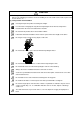
CAUTION 3. Various precautions Observe the following precautions. Incorrect handling of the unit could lead to faults, injuries and electric shocks, etc. (1) Transportation and installation Correctly transport the product according to its weight. Use the motor's hanging bolts only when transporting the motor. Do not transport the machine when the motor is installed on the machine. Do not stack the products above the tolerable number.
CAUTION Store and use the units under the following environment conditions.
CAUTION (2) Wiring Correctly and securely perform the wiring. Failure to do so could lead to abnormal operation of the motor. Do not install a condensing capacitor, surge absorber or radio noise filter on the output side of the drive unit. Correctly connect the output side of the drive unit (terminals U, V, W). Failure to do so could lead to abnormal operation of the motor. When using a power regenerative power supply unit, always install an AC reactor for each power supply unit.
CAUTION (3) Trial operation and adjustment Check and adjust each program and parameter before starting operation. Failure to do so could lead to unforeseen operation of the machine. Do not make remarkable adjustments and changes of parameter as the operation could become unstable. The usable motor and unit combination is predetermined. Always check the models before starting trial operation. If the axis is unbalanced due to gravity, etc., balance the axis using a counterbalance, etc.
CAUTION (5) Troubleshooting If a hazardous situation is predicted during power failure or product trouble, use a servomotor with magnetic brakes or install an external brake mechanism. Use a double circuit configuration that allows the operation circuit for the magnetic brakes to be operated even by the external emergency stop signal. Shut off with the servomotor brake control output. Servomotor MBR Shut off with NC brake control PLC output.
CAUTION (8) Transportation The unit and motor are precision parts and must be handled carefully. According to a United Nations Advisory, the battery unit and battery must be transported according to the rules set forth by the International Civil Aviation Organization (ICAO), International Air Transportation Association (IATA), International Maritime Organization (IMO), and United States Department of Transportation (DOT), etc.
Treatment of waste The following two laws will apply when disposing of this product. Considerations must be made to each law. The following laws are in effect in Japan. Thus, when using this product overseas, the local laws will have a priority. If necessary, indicate or notify these laws to the final user of the product. 1. Requirements for "Law for Promotion of Effective Utilization of Resources" (1) Recycle as much of this product as possible when finished with use.
Disposal (Note) This symbol mark is for EU countries only. This symbol mark is according to the directive 2006/66/EC Article 20 Information for endusers and Annex II. Your MITSUBISHI ELECTRIC product is designed and manufactured with high quality materials and components which can be recycled and/or reused. This symbol means that batteries and accumulators, at their end-of-life, should be disposed of separately from your household waste.
本製品の取扱いについて ( 日本語 /Japanese) 本製品は工業用 ( クラス A) 電磁環境適合機器です。販売者あるいは使用者はこの点に注意し、住商業環境以外で の使用をお願いいたします。 Handling of our product (English) This is a class A product. In a domestic environment this product may cause radio interference in which case the user may be required to take adequate measures. 본 제품의 취급에 대해서 ( 한국어 /Korean) 이 기기는 업무용 (A 급 ) 전자파적합기기로서 판매자 또는 사용자는 이 점을 주의하시기 바라며 가정외의 지역에 서 사용하는 것을 목적으로 합니다 .
CONTENTS 1. Introduction 1-1 System configuration ............................................................................................................................... 1-2 1-2 Explanation of type .................................................................................................................................. 1-3 1-2-1 Servomotor type.........................................................................................................................
6-1-5 Oil and waterproofing measures................................................................................................ 6-4 6-1-6 Cable stress ............................................................................................................................... 6-5 6-2 Installation of the units ............................................................................................................................. 6-6 6-2-1 Environmental conditions..................................
9-3-4 Improvement of protrusion at quadrant changeover................................................................ 9-19 9-3-5 Improvement of overshooting .................................................................................................. 9-24 9-3-6 Improvement of characteristics during acceleration/deceleration ........................................... 9-26 9-4 Settings for emergency stop....................................................................................................
Appendix 4-5-1 Measures for wiring in panel....................................................................................A4-5 Appendix 4-5-2 Measures for shield treatment .................................................................................A4-5 Appendix 4-5-3 Servo/spindle motor power cable ............................................................................A4-6 Appendix 4-5-4 Servo/spindle motor feedback cable .......................................................................
1. Introduction 1-1 System configuration.......................................................................................................................... 1-2 1-2 Explanation of type............................................................................................................................. 1-3 1-2-1 Servomotor type .......................................................................................................................... 1-3 1-2-2 Servo drive unit type................
1.
1. Introduction 1-2 Explanation of type 1-2-1 Servomotor type HF Series MITSUBISHI AC Motor t ype INPUT 3AC 155 V xxx A OUTPUT x. xkW I EC 34 -1 1994 3000r/min SER .N o.xxxxxxxx※ D AT E 04-1 Rated output Rated rotation speed Serial No .
1. Introduction 1-2-2 Servo drive unit type Motor type MITSUBISHI TYPE Rated input POWER INPUT SERVO DRIVE UNIT MDS-R-V1-40 1.0kW 6A 0.1A OUTPUT 6.6A Rated output 3PH 200-230V 50/60Hz DC24V 3PH 155V 0-240Hz MANUAL *BNP-C3045 S/W BNDXXXXXXXXX SERIAL# XXXXXXXXXXX Current state Serial No. H/W VER.
2. Specifications 2-1 Servomotor......................................................................................................................................... 2-2 2-1-1 Specifications list......................................................................................................................... 2-2 2-1-2 Torque characteristics ................................................................................................................. 2-3 2-1-3 Outline dimension drawings .......
2. Specifications 2-1 Servomotor 2-1-1 Specifications list HF Series HF□□-A48/A51 4000r/min Series Servomotor type Compatible servo drive unit type (Note 4) Rated output Rated current Continuous Rated torque characteristics Stall current Stall torque 2000r/min Series 3000r/min Series HF 75 HF 105 HF 54 HF 104 HF 154 HF 224 HF 204 HF 354 HF 123 HF 223 HF 303 HF 142 HF 302 MDS-R-V1/V2- 20 20 20 40 60 60 60 80 20 40 60 20 40 [kW] [A] 0.4 0.75 0.5 1.0 1.5 2.2 2.0 3.
2.
2. Specifications 2-1-3 Outline dimension drawings 1. Use a friction coupling (Spun ring, etc.) to connect with the load. CAUTION 2. Attach the cannon connector facing downward to improve the splash-proof performance. 3. When hanging up a motor with hanging bolts, stick them to the bearing surface of the hanging bolts.
2. Specifications [Unit:mm] ・HF75S-A48 3 45q Ǿ 10 50.9 Ǿ36 25 غ90 0 88.5 7.5 Ǿ80h7 38 33 5.5 Ǿ14h6 126.5 4-Ǿ6.6 mounting hole Use a hexagon socket bolt. 8 11 Oil seal Ǿ Detector connector 13 CM10-R10P 21 Power connector 54 61 CE05-2A18-10PD ・HF75BS-A48 33 7.5 3 10 0 Detector connector CM10-R10P 88.5 50.9 63.4 Oil seal 12.5 45q Ǿ Ǿ36 25 غ90 Ǿ80h7 5.5 38 Ǿ14h6 167.5 4-Ǿ6.6 mounting hole Use a hexagon socket bolt.
2. Specifications [Unit:mm] ・HF75T-A48 44 5.5 30 7.5 3 18 12 8.9 Ǿ36 Ǿ18 A Ǿ14 50.9 Ǿ 10 0 U nut M8x1.0 Plain washer 8 13 45q Ǿ1 18 A 14 غ90 88.5 14 Ǿ80h7 38 4-Ǿ6.6 mounting hole Use a hexagon socket bolt. M8X1.0 screw 126.5 5 -0.03 Taper 1/10 Oil seal 21 0 Detector connector CM10-R10P 61 3.55 Power connector CE05-2A18-10PD 54 0 5 -0.03 A-A ・HF75BT-A48 7.5 30 3 18 12 14 8.9 غ90 11 8 61 0 Power connector CE05-2A18-10PD 54 0 5 -0.03 Ǿ36 3.
2. Specifications [Unit:mm] ・HF75S-A51 33 5.5 7.5 3 ޓ Ǿ 10 0 88.5 60.2 Ǿ36 25 غ90 45q Ǿ80h7 41.5 Ǿ14h6 130 4-Ǿ6.6 mounting hole Use a hexagon socket bolt. 8 11 Oil seal Ǿ 12 Detector connector CM10-R10P Power connector 10 CE05-2A18-10PD 21 54 61 ・HF75BS-A51 33 غ90 3 60.2 63.4 Oil seal 12 Detector connector CM10-R10P 10 69 61 12.5 Brake connector CM10-R2P Power connector CE05-2A18-10PD 2-7 45 11 8 Ǿ36 25 Ǿ qޓ Ǿ80h7 7.5 Ǿ14h6 5.5 41.5 10 88.5 171 4-Ǿ6.
2. Specifications [Unit:mm] ・HF75T-A51 44 5.5 14 30 3 18 12 7.5 45 Ǿ1 18 Ǿ80h7 Ǿ36 5 -0.03 Power connector CE05-2A18-10PD 61 54 0 0 21 0 Ǿ 5 -0.03 3.55 10 Ǿ18 A Ǿ14 60.2 Detector connector CM10-R10P 10 U nut M8x1.0 Plain washer 8 Taper 1/10 Oil seal 12 qޓ 8.9 A 14 غ90 88.5 41.5 4-Ǿ6.6 mounting hole Use a hexagon socket bolt. M8X1.0 screw 130 A-A ・HF75BT-A51 44 5.5 7.5 30 3 18 12 Ǿ36 Ǿ18 A Ǿ14 60.2 63.4 10 61 54 5 3.
2. Specifications [Unit:mm] ・HF105S-A48 7.5 3 45q Ǿ 10 50.9 Ǿ36 25 غ90 0 88.5 38 Ǿ80h7 33 5.5 Ǿ14h6 162.5 4-Ǿ6.6 mounting hole Use a hexagon socket bolt. 8 11 Oil seal Ǿ 13 Detector connector CM10-R10P 21 54 97 Power connector CE05-2A18-10PD ・HF105BS-A48 203.5 4-Ǿ6.6 mounting hole Use a hexagon socket bolt. 33 5.5 3 10 0 Detector connector CM10-R10P 88.5 50.9 63.4 Oil seal 12.5 45q Ǿ Ǿ36 25 غ90 Ǿ80h7 7.
2. Specifications [Unit:mm] ・HF105T-A48 4-Ǿ6.6 mounting hole Use a hexagon socket bolt. غ90 44 M8X1.0 screw 5.5 38 14 30 7.5 3 18 12 8.9 Ǿ36 Ǿ18 A Ǿ14 50.9 Ǿ 10 0 U nut M8x1.0 Plain washer 8 Taper 1/10 13 Detector connector CM10-R10P Ǿ80h7 A 14 45q Ǿ1 18 88.5 162.5 Oil seal 21 54 0 0 Power connector CE05-2A18-10PD 5 -0.03 97 3.55 5 -0.03 A-A ・HF105BT-A48 44 5.5 7.5 30 3 18 12 8.9 Ǿ36 66 Brake connector CM10-R2P U nut M8x1.
2. Specifications [Unit:mm] ・HF105S-A51 7.5 3 60.2 10 Oil seal 12 Detector connector CM10-R10P Power connector 10 CE05-2A18-10PD 45 11 8 Ǿ36 25 غ90 Ǿ qޓ 88.5 41.5 Ǿ80h7 33 5.5 Ǿ14h6 166 4-Ǿ6.6 mounting hole Use a hexagon socket bolt. 0 Ǿ 21 54 97 ・HF105BS-A51 7.5 3 60.2 63.4 Ǿ36 25 Oil seal 45q 11 8 ޓ 10 88.5 41.5 غ90 Ǿ Ǿ80h7 33 5.5 Ǿ14h6 207 4-Ǿ6.6 mounting hole Use a hexagon socket bolt. 0 Ǿ 12 Detector connector CM10-R10P 10 12.
2. Specifications [Unit:mm] ・HF105T-A51 14 30 3 18 12 7.5 غ90 Ǿ1 8.9 Ǿ14 60.2 10 Ǿ 0 -0.03 97 Power connector CE05-2A18-10PD 54 0 5 -0.03 5 21 q 18 0 U nut M8x1.0 Plain washer 8 Taper 1/10 Oil seal 12 Detector connector CM10-R10P 3.55 10 Ǿ18 A Ǿ36 A 14 45 88.5 5.5 41.5 4-Ǿ6.6 mounting hole Use a hexagon socket bolt. M8X1.0 screw 44 Ǿ80h7 166 A-A ・HF105BT-A51 44 5.5 7.5 30 3 18 12 11 8 Ǿ36 Ǿ18 A Ǿ14 60.2 63.
2. Specifications [Unit:mm] ・HF54S-A48 4-Ǿ9 mounting hole Use a hexagon socket bolt. 118.5 12 45q 3 Ǿ 50 5 50.9 Ǿ110h7 Ǿ24h6 16 14 13 112.5 38.2 غ130 55 5 Ǿ Oil seal Detector connector CM10-R10P 20.9 Power connector CE05-2A18-10PD 13.5 57.8 58 ・HF54BS-A48 4-Ǿ9 mounting hole Use a hexagon socket bolt. 153 12 55 3 50 غ130 45q Ǿ 16 5 14 13 112.5 79.9 50.9 Ǿ110h7 Ǿ24h6 43.5 5 Ǿ Oil seal 59 Detector connector CM10-R10P Brake connector CM10-R2P 20.9 57.
2. Specifications [Unit:mm] ・HF54T-A48 4-Ǿ9 mounting hole Use a hexagon socket bolt. 3 28 12 25 10 Ǿ 16 5 Plain washer 10 14 112.5 A 50.9 Ǿ16 18 45q Ǿ110h7 12 A 38.2 غ130 58 M10X1.25 screw 118.5 5 Ǿ 13 U nut M101.25 Tightening torque 23 to 30 Nm Taper 1/10 0 Oil seal 5 -0.03 Detector connector CM10-R10P 57.8 5 Power connector CE05-2A18-10PD 13.5 58 4.3 0 -0.03 20.9 A-A ・HF54BT-A48 58 12 3 18 28 12 13 20.9 57.8 5 Ǿ110h7 A 0 5-0.03 4.
2. Specifications [Unit:mm] ・HF54S-A51 4-Ǿ9 mounting hole Use a hexagon socket bolt. 122 غ130 55 41.7 12 45 3 Ǿ 16 q ޓ 5 10 14 5 Ǿ Oil seal 12 112.5 60.2 Ǿ110h7 Ǿ24h6 50 Detector connector CM10-R10P 24 20.9 Power connector CE05-2A18-10PD 13.5 57.8 58 ・HF54BS-A51 4-Ǿ9 mounting hole Use a hexagon socket bolt. 55 Ǿ4 Ǿ24h6 50 16 10 5 14 12 24 5q ޓ Ǿ 79.9 60.2 غ130 3 Ǿ110h7 12 5 Ǿ Oil seal 62 Detector connector CM10-R10P Brake connector CM10-R2P 20.9 57.
2. Specifications [Unit:mm] ・HF54T-A51 4-Ǿ9 mounting hole Use a hexagon socket bolt. 58 3 28 12 25 10 60.2 45 Ǿ 16 q 5 Ǿ110h7 A 18 A 12 Ǿ16 41.7 غ130 M10X1.25 screw 122 5 14 U nut M101.25 Ǿ Tightening torque 23 to 30 Nm Taper 1/10 0 5 -0.03 13.5 Oil seal 10 12 Detector connector CM10-R10P 0 5 -0.03 20.9 57.8 Power connector CE05-2A18-10PD 4.3 24 112.5 Plain washer 10 58 A-A ・HF54BT-A51 58 3 28 25 10 45 Ǿ 16 qޓ 5 20.9 57.8 Power connector CE05-2A18-10PD 79.9 5 4.
2. Specifications [Unit:mm] ・HF104S-A48 4-Ǿ9 mounting hole Use a hexagon socket bolt. 140.5 غ130 55 12 45q 3 Ǿ 50 50.9 13 5 Ǿ110h7 Ǿ24h6 16 14 112.5 38.2 5 Ǿ Oil seal Detector connector CM10-R10P 20.9 Power connector CE05-2A18-10PD 13.5 79.8 58 ・HF104BS-A48 4-Ǿ9 mounting hole Use a hexagon socket bolt. 175 45q 3 16 5 14 13 112.5 Ǿ24h6 50.9 Ǿ Ǿ110h7 12 50 79.9 غ130 55 43.5 5 Ǿ Oil seal 59 Detector connector CM10-R10P Brake connector CM10-R2P 20.9 79.
2. Specifications [Unit:mm] ・HF104T-A48 4-Ǿ9 mounting hole Use a hexagon socket bolt. غ130 58 3 28 12 Ǿ16 18 A 50.9 A 25 10 45q Ǿ 16 5 Plain washer 10 14 U nut M101.25 Ǿ Tightening torque 23 to 30 Nm Taper 1/10 13 Detector connector CM10-R10P Oil seal 0 58 4.3 Power connector CE05-2A18-10PD 0 79.8 5 13.5 5 -0.03 5 -0.03 20.9 112.5 12 Ǿ110h7 38.2 M10X1.25 screw 140.5 A-A ・HF104BT-A48 3 18 28 12 A Ǿ16 50.9 45q Ǿ 16 5 Plain washer 10 14 13 59 20.9 79.
2. Specifications [Unit:mm] ・HF104S-A51 144 4-Ǿ9 mounting hole Use a hexagon socket bolt. 55 غ130 50 41.7 12 45 3 Ǿ qޓ 5 14 10 5 Ǿ Oil seal 12 112.5 60.2 Ǿ110h7 Ǿ24h6 16 Detector connector CM10-R10P 24 20.9 13.5 79.8 Power connector CE05-2A18-10PD 58 ・HF104BS-A51 47 12 55 50 غ130 Ǿ4 3 Ǿ 5q 5 79.9 Ǿ110h7 60.2 Ǿ24h6 16 10 14 12 5 Ǿ Oil seal 24 62 Detector connector CM10-R10P Brake connector CM10-R2P 20.9 79.8 Power connector CE05-2A18-10PD 2 - 19 13.
2. Specifications [Unit:mm] ・HF104T-A51 144 58 3 28 12 25 10 A 60.2 غ130 45 Ǿ 16 qޓ 5 Ǿ110h7 A 18 Ǿ16 12 41.7 M10X1.25 screw 4-Ǿ9 mounting hole Use a hexagon socket bolt. 10 14 U nut M101.25 Ǿ Tightening torque 23 to 30 Nm Taper 1/10 0 5 -0.03 Oil seal 12 5 20.9 79.8 Power connector CE05-2A18-10PD 5 4.3 24 0 -0.03 Detector connector CM10-R10P 112.5 Plain washer 10 13.5 58 A-A ・HF104BT-A51 58 3 25 10 45 Ǿ q ޓ 5 Ǿ110h7 16 20.9 79.
2. Specifications [Unit:mm] ・HF154S-A48 4-Ǿ9 mounting hole Use a hexagon socket bolt. 162.5 غ130 55 12 45q 3 Ǿ 50 50.9 13 5 Ǿ110h7 Ǿ24h6 16 14 112.5 38.2 5 Ǿ Oil seal Detector connector CM10-R10P 20.9 13.5 101.8 Power connector CE05-2A18-10PD 58 ・HF154BS-A48 4-Ǿ9 mounting hole Use a hexagon socket bolt. 197 غ130 55 12 Ǿ4 3 Ǿ 16 5q 5 Ǿ110h7 50.9 79.9 Ǿ24h6 50 14 13 112.5 43.
2. Specifications [Unit:mm] ・HF154T-A48 4-Ǿ9 mounting hole Use a hexagon socket bolt. غ130 58 A 45q Ǿ 16 5 Plain washer 10 14 U nut M10x1.25 Tightening torque 23 to 30 Nm Taper 1/10 Oil seal 13 Detector connector CM10-R10P 20.9 112.5 25 10 A 28 12 M10X1.25 screw 3 18 Ǿ16 12 50.9 38.2 Ǿ110h7 162.5 5 Ǿ 13.5 101.8 Power connector CE05-2A18-10PD 58 0 4.3 0 5 -0.03 5 -0.03 A-A 58 12 3 18 28 12 10 Ǿ 16 A A Ǿ16 50.9 79.9 Plain washer 10 13 0 101.8 0 5-0.03 4.3 20.
2. Specifications [Unit:mm] ・HF154S-A51 166 4-Ǿ9 mounting hole Use a hexagon socket bolt. 55 غ130 50 41.7 12 45 3 Ǿ q ޓ 5 14 10 5 Ǿ Oil seal 12 112.5 60.2 Ǿ110h7 Ǿ24h6 16 Detector connector CM10-R10P 24 20.9 13.5 101.8 Power connector CE05-2A18-10PD 58 ・HF154BS-A51 47 12 55 50 غ130 Ǿ4 3 Ǿ 5 79.9 10 14 12 24 5q Ǿ110h7 60.2 Ǿ24h6 16 5 Ǿ 62 Detector connector CM10-R10P Brake connector CM10-R2P Oil seal 20.9 101.
2. Specifications [Unit:mm] ・HF154T-A51 166 58 3 28 12 25 10 45 Ǿ 16 60.2 q 5 Ǿ110h7 A 18 غ130 A 12 Ǿ16 41.7 M10X1.25 screw 4-Ǿ9 mounting hole Use a hexagon socket bolt. 10 U nut M10x1.25 Tightening torque 23 to 30 Nm Taper 1/10 Oil seal 12 Detector connector CM10-R10P 101.8 5 Power connector CE05-2A18-10PD 0 -0.03 20.9 5 Ǿ 0 5 -0.03 13.5 4.3 24 14 112.5 Plain washer 10 58 A-A 58 3 A 10 16 5 Ǿ110h7 60.2 Plain washer 10 0 -0.03 101.8 5 4.3 20.
2. Specifications [Unit:mm] ・HF224S-A48 4-Ǿ9 mounting hole Use a hexagon socket bolt. 55 12 130 SQ. 3ޓ 16 24 h6 DIA. 50.9 13 45 IA Oil seal 1 Detector connector CM10-R10P 45 DI A. 13.5 20.9 123.8 Power connector CE05-2A18-10PD q . 110h7 DIA. 50 5D 112.5 184.5 38.2 58 ・HF224BS-A48 4-Ǿ9 mounting hole Use a hexagon socket bolt. 130 SQ. 55 12 43.5 16 3ޓ 13 Detector connector IA 45 q . 110h7 DIA. 50.9 79.9 24 h6 DIA. 50 5D 112.5 219 A.
2. Specifications [Unit:mm] ・HF224T-A48 M10 1.25 screw 58 12 3ޓ 28 12 5D 45 IA q ޓ . 110 h7 DIA. A 50.9 16 25 10 A 16 DIA. 18 Plain washer 10 5 14 DI A. 112.5 184.5 38.2 4-Ǿ9 mounting hole Use a hexagon socket bolt. 130 SQ. 13 U nut M10 1.25 Tightening torque 23 to 30 Nm Taper 1/10 Detector connector CM10-R10P 20.9 123.8 58 Oil seal 0 5ޓ -0.03 4.3 0 5ޓ -0.03 Power connector CE05-2A18-10PD 13.5 A-A ・HF224BT-A48 58 3ޓ 18 28 12 16 14 123.8 5D q IA.
2. Specifications [Unit:mm] ・HF224S-A51 4-Ǿ9 mounting hole Use a hexagon socket bolt. 188 55 130 SQ. 16 3ޓ 12 45 IA 24 h6 DIA. 60.2 10 Oil seal 12 1 Detector connector CM10-R10P 45 DI A. 20.9 24 13.5 123.8 Power connector CE05-2A18-10PD qޓ . 110h7 DIA. 50 5D 112.5 41.7 58 ・HF224BS-A51 4-Ǿ9 mounting hole Use a hexagon socket bolt. 55 12 130 SQ. 16 3ޓ IA 24 42.
2. Specifications [Unit:mm] ・HF224T-A51 12 28 25 10 60.2 A A 18 16 45 5D IA . Plain washer 10 10 12 1 Detector connector CM10-R10P 24 123.8 DI A. 13.5 58 4.3 0 5 -0.03 Power connector CE05-2A18-10PD 45 U nut M10 1.25 Tightening torque 23 to 30 Nm Taper 1/10 Oil seal 0 5-0.03 20.9 qޓ 112.5 3 16 DIA. 12 M10 1.25 screw 58 41.7 110h7 DIA. 188 4-Ǿ9 mounting hole Use a hexagon socket bolt. 130 SQ. A-A ・HF224BT-A51 16 3 18 28 12 10 A 16 DIA. 60.2 A 25 D 45 20.
2. Specifications [Unit:mm] ・HF204S-A48 4-Ǿ13.5 mounting hole Use a hexagon socket bolt. 143.5 38.5 غ176 79 18 3 75 45q Ǿ 0 13 Oil seal 20 140.9 50.9 Ǿ114.3 0 -0.025 Ǿ35 +0.010 0 23 0 Ǿ Detector connector CM10-R10P 24.8 Power connector CE05-2A22-22PD 82 79.8 ・HF204BS-A48 4-Ǿ13.5 mounting hole Use a hexagon socket bolt. 193 45.5 غ176 79 18 3 45q Ǿ 23 0 -0.0.25 0 13 Oil seal 20 140.9 Ǿ114.3 50.9 96.9 Ǿ35 +0.010 0 75 0 Ǿ Detector connector CM10-R10P 44 66.
2. Specifications [Unit:mm] ・HF204S-A51 147 4-Ǿ13.5 mounting hole Use a hexagon socket bolt. 79 غ176 75 3 18 45 Ǿ 23 q ޓ 0 10 12 Oil seal 20 140.9 60.2 Ǿ114.3 0 -0.025 Ǿ35 +0.010 0 42 0 Ǿ Detector connector CM10-R10P 24.8 24 79.8 Power connector CE05-2A22-22PD 82 ・HF204BS-A51 4-Ǿ13.5 mounting hole Use a hexagon socket bolt. 196.5 غ176 79 49 18 3 45 Ǿ 23 24 44 Detector connector 69.5 CM10-R10P Brake connector CM10-R2P Power connector CE05-2A22-22PD 0 -0.0.
2. Specifications [Unit:mm] ・HF354S-A48 4-Ǿ13.5 mounting hole Use a hexagon socket bolt. 176 SQ. 79 183.5 2-M8 Suspension bolt hole 38.5 23 3ޓ 18 0 A. DIA. qޓ 13 Oil seal 2 00 DI 140.9 50.9 114.3 35 0 -0.025 DIA. 75 +0.010 0 45 DI A. Detector connector CM10-R10P 24.8 82 119.8 Power connector CE05-2A22-22PD ・HF354BS-A48 4-Ǿ13.5 mounting hole Use a hexagon socket bolt. 79 18 45.5 176 SQ. 23 3ޓ 0 0 -0.0.25 DIA. 45 q A.
2. Specifications [Unit:mm] ・HF354S-A51 4-Ǿ13.5 mounting hole Use a hexagon socket bolt. 79 18 42 23 3ޓ 176 SQ. 0 DIA. 0 -0.025 45 q A. ޓ 60.2 114.3 35 +0.010 0 75 DI DIA. 187 2-M8 Suspension bolt hole 12 Oil seal 2 00 DI 140.9 10 24 A. Detector connector CM10-R10P Power connector CE05-2A22-22PD 24.8 119.8 82 ・HF354BS-A51 4-Ǿ13.5 mounting hole Use a hexagon socket bolt. 79 18 23 3ޓ 176 SQ. 0 10 24 Detector connector CM10-R10P 44 0 -0.025 DIA.
2. Specifications [Unit:mm] ・HF123S-A48 4-Ǿ9 mounting hole Use a hexagon socket bolt. 140.5 130 SQ. 55 16 3ޓ 5D IA 45 . q 50.9 24 h6 DIA. 110h7 DIA. 50 13 Oil seal Detector connector 1 45 DI 112.5 12 38.2 A. CM10-R10P 20.9 Power connector 13.5 79.8 58 CE05-2A18-10PD ・HF123BS-A48 4-Ǿ9 mounting hole Use a hexagon socket bolt. 55 12 43.5 130 SQ. 16 3ޓ 5D 45 IA q . CM10-R10P Brake connector CM10-R2P Power connector CE05-2A18-10PD 20.9 79.
2. Specifications [Unit:mm] ・HF123T-A48 M101.25 screw 58 3ޓ 28 12 16 5D A 50.9 Plain washer 10 5 14 13 Detector connector CM10-R10P q ޓ . DI A. U nut M101.25 Tightening torque 23 to 30 Nm Taper 1/10 20.9 Oil seal 79.8 13.5 58 0 5ޓ -0.03 4.3 0 5ޓ -0.03 Power connector CE05-2A18-10PD 45 IA 25 10 A 16 DIA. 18 130 SQ. 112.5 12 110h7 DIA. 140.5 38.2 4-Ǿ9 mounting hole Use a hexagon socket bolt. A-A ・HF123BT-A48 12 3ޓ 18 28 12 M101.25 screw 58 175 43.
2. Specifications [Unit:mm] ・HF123S-A51 4-Ǿ9 mounting hole Use a hexagon socket bolt. 55 130 SQ. 16 3ޓ 12 5D 45 IA 24 h6 DIA. 60.2 10 12 Oil seal 1 45 DI A. Detector connector CM10-R10P 24 13.5 20.9 Power connector CE05-2A18-10PD q . 110h7 DIA. 50 112.5 144 41.7 58 79.8 ・HF123BS-A51 4-Ǿ9 mounting hole Use a hexagon socket bolt. 55 12 130 SQ. 3ޓ 16 IA 10 Oil seal 24 42.5 12 Detector connector 62 CM10-R10P Brake connector CM10-R2P Power connector CE05-2A18-10PD 20.9 79.
2. Specifications [Unit:mm] ・HF123T-A51 M101.25 screw 58 3 18 28 12 16 5D 45 IA qޓ . 25 10 60.2 A 16 DIA. 12 110h7 DIA. 41.7 130 SQ. A 144 4-Ǿ9 mounting hole Use a hexagon socket bolt. 10 112.5 Plain washer 10 A. 12 45 1 U nut M101.25 Tightening torque 23 to 30 Nm Detector connector CM10-R10P 24 20.9 13.5 Taper 1/10 Oil seal 79.8 Power connector CE05-2A18-10PD DI 58 0 4.3 0 5 -0.03 5 -0.03 A-A ・HF123BT-A51 58 12 3ޓ 18 28 12 M101.25 screw 178.
2. Specifications [Unit:mm] ・HF223S-A48 4-Ǿ9 mounting hole Use a hexagon socket bolt. 55 12 130 SQ. 3ޓ 16 24 h6 DIA. 50.9 13 45 IA . A. Oil seal 5 14 Detector connector CM10-R10P DI 13.5 20.9 123.8 Power connector CE05-2A18-10PD q 110h7 DIA. 50 5D 112.5 184.5 38.2 58 ・HF223BS-A48 4-Ǿ9 mounting hole Use a hexagon socket bolt. 130 SQ. 55 12 43.5 16 3ޓ 13 Detector connector Oil seal 1 59 IA 45 q . 110h7 DIA. 50.9 79.9 24 h6 DIA. 50 5D 45 DI 112.5 219 A.
2. Specifications [Unit:mm] ・HF223T-A48 M10 1.25 screw 58 12 3ޓ 28 12 5D 45 IA q ޓ . 110 h7 DIA. A 50.9 16 25 10 A 16 DIA. 18 Plain washer 10 5 14 DI A. 112.5 184.5 38.2 4-Ǿ9 mounting hole Use a hexagon socket bolt. 130 SQ. 13 U nut M10 1.25 Tightening torque 23 to 30 Nm Taper 1/10 Detector connector CM10-R10P 20.9 123.8 58 Oil seal 0 5ޓ -0.03 4.3 0 5ޓ -0.03 Power connector CE05-2A18-10PD 13.5 A-A ・HF223BT-A48 58 3ޓ 18 28 12 16 123.8 5 14 DIA U nut M101.
2. Specifications [Unit:mm] ・HF223S-A51 4-Ǿ9 mounting hole Use a hexagon socket bolt. 188 55 130 SQ. 16 3ޓ 12 45 IA 24 h6 DIA. 60.2 10 Oil seal 12 Detector connector CM10-R10P 5 14 DI A. 20.9 24 13.5 123.8 Power connector CE05-2A18-10PD qޓ . 110h7 DIA. 50 5D 112.5 41.7 58 ・HF223BS-A51 4-Ǿ9 mounting hole Use a hexagon socket bolt. 55 12 130 SQ. 16 3ޓ IA 24 42.5 Oil seal 12 Detector connector 62 CM10-R10P Brake connector CM10-R2P Power connector CE05-2A18-10PD 5 14 20.
2. Specifications [Unit:mm] ・HF223T-A51 12 28 25 10 60.2 A A 18 16 45 5D IA . Plain washer 10 10 12 1 Detector connector CM10-R10P 24 123.8 DI A. 13.5 58 4.3 0 5 -0.03 Power connector CE05-2A18-10PD 45 U nut M10 1.25 Tightening torque 23 to 30 Nm Taper 1/10 Oil seal 0 5-0.03 20.9 qޓ 112.5 3 16 DIA. 12 M10 1.25 screw 58 41.7 110h7 DIA. 188 4-Ǿ9 mounting hole Use a hexagon socket bolt. 130 SQ. A-A ・HF223BT-A51 10 A 16 DIA. 60.2 A 25 . D 45 20.9 123.
2. Specifications [Unit:mm] ・HF303S-A48 4-Ǿ13.5 mounting hole Use a hexagon socket bolt. 183.5 79 176 SQ. 3ޓ 23 0 45 DI q 13 Oil seal 0 20 Detector connector CM10-R10P DI 140.9 50.9 114.3 DIA. DIA. A. 35 +0.010 0 75 0 -0.025 18 38.5 A. 24.8 Power connector CE05-2A22-22PD 82 119.8 ・HF303BS-A48 4-Ǿ13.5 mounting hole Use a hexagon socket bolt. 233 176 SQ. 79 18 45.5 3ޓ 23 75 0 45 DI 44 ޓ DIA. 0 -0.0.25 DIA. q 13 Oil seal 2 Detector connector 66.
2. Specifications [Unit:mm] ・HF303S-A51 4-Ǿ13.5 mounting hole Use a hexagon socket bolt. 187 176 SQ. 79 18 42 23 3ޓ 0 45 q ޓ DIA. A. 60.2 114.3 0 -0.025 DIA. 35 DIA. +0.010 0 75 DI Oil seal 12 140.9 10 24 A. 0 20 DI Detector connector CM10-R10P 24.8 82 119.8 Power connector CE05-2A22-22PD ・HF303BS-A51 4-Ǿ13.5 mounting hole Use a hexagon socket bolt. 79 176 SQ. 23 3ޓ 0 0 -0.025 DIA. A. Oil seal 0 20 44 12 Detector connector 69.
2. Specifications [Unit:mm] ・HF142S-A48 4-Ǿ9 mounting hole Use a hexagon socket bolt. 55 12 38.2 130 SQ. 3ޓ 5D q ޓ IA 50 24 h6 DIA. 110h7 DIA. . 50.9 13 45 16 Oil seal 1 45 DI 112.5 162.5 A. Detector connector CM10-R10P 20.9 13.5 101.8 Power connector CE05-2A18-10PD 58 ・HF142BS-A48 4-Ǿ9 mounting hole Use a hexagon socket bolt. 197 130 SQ. 55 12 3ޓ 16 Oil seal 13 59 Detector connector CM10-R10P Brake connector CM10-R2P Power connector CE05-2A18-10PD 5D 5 14 20.
2. Specifications [Unit:mm] ・HF142T-A48 M101.25 screw 58 12 3ޓ 28 12 5D 45 IA q ޓ . 110 h7 DIA. A 50.9 16 25 10 A 16 DIA. 18 130 SQ. Plain washer 10 IA. 112.5 162.5 38.2 4-Ǿ9 mounting hole Use a hexagon socket bolt. 5D 14 13 U nut M101.25 Tightening torque 23 to 30 Nm Detector connector CM10-R10P Taper 1/10 20.9 58 0 5ޓ -0.03 4.3 0 5ޓ -0.03 Power connector CE05-2A18-10PD 13.5 Oil seal 101.8 A-A ・HF142BT-A48 58 3ޓ 16 5 14 20.9 101.8 45 .
2. Specifications [Unit:mm] ・HF142S-A51 4-Ǿ9 mounting hole Use a hexagon socket bolt. 130 SQ. 55 3ޓ 12 16 45 IA 10 Oil seal 12 1 45 DI A. Detector connector CM10-R10P 24 13.5 20.9 58 101.8 Power connector CE05-2A18-10PD q . 110h7 DIA. 60.2 24 h6 DIA. 50 5D 112.5 166 41.7 ・HF142BS-A51 4-Ǿ9 mounting hole Use a hexagon socket bolt. 130 SQ. 55 12 16 3ޓ 45 IA 10 Oil seal 1 24 42.
2. Specifications [Unit:mm] ・HF142T-A51 4-Ǿ9 mounting hole Use a hexagon socket bolt. 130 SQ. 12 25 10 16 A 60.2 5D 45 IA q . 110h7 DIA. 28 A 18 16 DIA. 3 12 M101.25 screw 58 166 41.7 112.5 Plain washer 10 A. 10 45 12 U nut M101.25 Tightening torque 23 to 30 Nm Taper 1/10 Oil seal 0 5 -0.03 Detector connector CM10-R10P 20.9 1 13.5 58 4.3 0 Power connector CE05-2A18-10PD 101.8 5 -0.03 24 DI A-A ・HF142BT-A51 60.2 A IA 45 . D 45 20.9 101.8 Oil seal 0 5 -0.03 4.
2. Specifications [Unit:mm] ・HF302S-A48 4-Ǿ13.5 mounting hole Use a hexagon socket bolt. 183.5 79 176 SQ. 3ޓ 23 0 75 45 DI DIA. 0 -0.025 q 13 Oil seal 0 20 Detector connector CM10-R10P DI 140.9 50.9 114.3 35 +0.010 0 A. DIA. 18 38.5 A. 24.8 Power connector CE05-2A22-22PD 82 119.8 ・HF302BS-A48 4-Ǿ13.5 mounting hole Use a hexagon socket bolt. 233 176 SQ. 79 23 44 DIA. 0 45 DI A. q ޓ 13 Oil seal 2 Detector connector 66.
2. Specifications [Unit:mm] ・HF302S-A51 4-Ǿ13.5 mounting hole Use a hexagon socket bolt. 187 176 SQ. 79 18 42 23 3ޓ 0 45 q ޓ DIA. A. 60.2 114.3 0 -0.025 DIA. 35 DIA. +0.010 0 75 DI Oil seal 12 0 20 DI 140.9 10 24 A. Detector connector CM10-R10P 24.8 82 119.8 Power connector CE05-2A22-22PD ・HF302BS-A51 4-Ǿ13.5 mounting hole Use a hexagon socket bolt. 79 176 SQ. 23 3ޓ 0 0 -0.025 DIA. +0.010 0 Oil seal 0 20 44 12 Detector connector 69.
2. Specifications 2-2 Servo drive unit 2-2-1 Installation environment conditions Common installation environment conditions for servo drive unit are shown below.
2. Specifications 2-2-3 Outline dimension drawings (1) 1-axis servo drive unit 40 MDS-R-V1-20 MDS-R-V1-40 (Note3) 10 ø6 hole 15 70 Wiring allowance 360 380 350 (Note3) 15 40 340 Intake 15 6 8 30 60 226 2-M5 screw hole 52 Panel mounting hole machining drawing 2 - 50 360 Square hole (Note 1) Attach packing around the square hole for sealing. The intake fan can be mounted only at the top as shown above.
2. Specifications 40 MDS-R-V1-60 MDS-R-V1-80 (Note3) 10 ø6 hole 15 70 Wiring allowance 360 380 350 (Note3) 15 40 340 Intake 15 6 8 45 90 226 Attach packing around the square hole for sealing. The intake fan can be mounted only at the top as shown above.
2. Specifications (2) 2-axis servo drive unit 40 MDS-R-V2-4040 (Note2) ø6 hole 10 70 Wiring allowance 15 MDS-R-V2-2020 MDS-R-V2-4020 360 380 350 340 Intake (Note2) 15 40 Intake 15 6 8 30 60 226 Attach packing around the square hole for sealing.
2. Specifications 40 MDS-R-V2-8080 70 Wiring allowance (Note2) ø6 hole 10 MDS-R-V2-8040 MDS-R-V2-8060 15 MDS-R-V2-6040 MDS-R-V2-6060 360 380 350 340 Intake (Note2) 15 40 Intake 15 6 8 45 90 226 Attach packing around the square hole for sealing.
2. Specifications 2-2-4 Explanation of each part (1) Explanation of each servo drive unit part <1> <2> <1> <2> <3> <3> <4> <5> <4> <5> <6> <7> <6> <7> <8> <8> <9> <10> <10> <11> <12> <12> <13> <13> <14> <14> <15> <16> <16> MDS-R-V1 (1-axis servo drive unit) MDS-R-V2 (2-axis servo drive unit) The connector layout differs according to the unit being used. Refer to each unit’s outline drawing for details.
3. Characteristics 3-1 Drive unit characteristics .................................................................................................................... 3-2 3-1-1 Heating value .............................................................................................................................. 3-2 3-1-2 Overload protection characteristics............................................................................................. 3-3 3-2 Servomotor.....................................
3. Characteristics 3-1 Drive unit characteristics 3-1-1 Heating value The heating value of each servo drive unit is the heating value at stall output.
3. Characteristics 3-1-2 Overload protection characteristics The servo drive unit has an electronic thermal relay to protect the servomotor and servo drive unit from overloads. The operation characteristics of the electronic thermal relay are shown below when standard parameters (SV021=60, SV022=150) are set. If overload operation over the electronic thermal relay protection curve shown below is carried out, overload 1 (alarm 50) will occur.
3. Characteristics (1)HF-75+V1-20、HF-44+V1-20 (2)HF75+V1-40、HF44+V1-40 1000 1000 100 100 Time (sec) 時間(sec) 10000 Time 時間(sec) (sec) 10000 10 10 1 1 0.1 0.1 0 100 200 300 モータ電流値(ストール定格電流値比 %) 400 500 0 100 Current (stall %) 1000 100 100 Time (sec) Time (sec) 時間(sec) 1000 時間(sec) 10000 10 1 500 400 500 400 500 0.
3. Characteristics (9)HF-154+V1-40、HF-153+V1-40 (10)HF-154+V1-60、HF-153+V1-60 1000 1000 100 100 Time (sec) Time (sec) 時間(sec) 10000 時間(sec) 10000 10 10 1 1 0.1 0.1 0 100 200 300 モータ電流値(ストール定格電流値比 %) 400 500 0 100 Current (stall %) 100 100 Time (sec) 10 時間(sec) 1000 Time (sec) 1000 時間(sec) 10000 1 500 400 500 400 500 0.
3. Characteristics (17)HF-354+V1-80、HF-353+V1-80 (18)HF-123+V1-20 1000 1000 100 100 Time (sec) Time (sec) 時間(sec) 10000 時間(sec) 10000 10 10 1 1 0.1 0.1 0 100 200 300 モータ電流値(ストール定格電流値比 %) 400 0 500 100 (19)HF-223+V1-40 1000 1000 100 100 Time (sec) Time (sec) 時間(sec) 10000 時間(sec) 10000 10 500 10 1 0.1 0.
3. Characteristics 3-2 Servomotor 3-2-1 Shaft characteristics There is a limit to the load that can be applied on the motor shaft. Make sure that the load applied on the radial direction and thrust direction, when mounted on the machine, is below the tolerable values given below. These loads may affect the motor output torque, so consider them when designing the machine.
3. Characteristics 3-2-2 Magnetic brake CAUTION 1. The axis will not be mechanically held even when the dynamic brakes are used. If the machine could drop when the power fails, use a servomotor with magnetic brakes or provide an external brake mechanism as holding means to prevent dropping. 2. The magnetic brakes are used for holding, and must not be used for normal braking.
3. Characteristics (2) Magnetic brake characteristics HF54B, HF104B, Motor type Item HF75B, HF105B, HF154B, HF224B, HF123B, HF223B, HF204B, HF354B, HF303B, HF302B HF142B Spring closed non-exciting operation magnetic brakes (for maintenance and emergency braking) Type (Note 1) Rated voltage DC24V Rated current at 20°C ( A) 0.38 0.8 1.4 Capacity ( W) 9 19 34 Static friction torque (N・m) 2.4 8.3 43.1 Inertia (Note 2) (kg・cm2) 0.2 2.2 9.6 Release delay time (Note 3) ( s) 0.03 0.
3. Characteristics (3) Magnetic brake power supply CAUTION 1. Always install a surge absorber on the brake terminal when using DC OFF. 2. Do not pull out the cannon plug while the brake power is ON. The cannon plug pins could be damaged by sparks. (a) Brake excitation power supply 1) 2) Prepare a brake excitation power supply that can accurately ensure the attraction current in consideration of the voltage fluctuation and excitation coil temperature. The brake terminal polarity is arbitrary.
3. Characteristics 3-2-3 Dynamic brake characteristics If a servo alarm that cannot control the motor occurs, the dynamic brakes will function to stop the servomotor regardless of the parameter settings. (1) Deceleration torque The dynamic brake uses the motor as a generator, and obtains the deceleration torque by consuming that energy with the dynamic brake resistance.
3. Characteristics (2) Coasting rotation distance during emergency stop The distance that the motor coasts (angle for rotary axis) when stopping with the dynamic brakes can be approximated with the following expression.
3. Characteristics Coasting amount calculation coefficients table Motor type HF75 HF105 HF54 HF104 Combination unit MDS-R-V1-20 MDS-R-V2-2020/4020 MDS-R-V1-20 MDS-R-V2-2020/4020 MDS-R-V1-20 MDS-R-V2-2020/4020 MDS-R-V1-40 MDS-R-V2-4020/4040 MDS-R-V2-6040/8040 HF154 MDS-R-V1-60 DB resistance value (Ω) Jm (kg・㎝ ) A×10 B×10 0 2.6 0.67 3.14 0 5.1 1.31 6.16 0 6.1 5.62 3.85 0 11.9 5.06 2.54 0.2 11.9 3.84 3.35 0.2 17.8 3.68 3.23 0.2 23.7 2.88 3.76 0.2 38.3 11.41 4.62 0.
3 - 14
4. Dedicated Options 4-1 Regenerative option ........................................................................................................................... 4-2 4-1-1 Regenerative resistor unit ........................................................................................................... 4-4 4-1-2 Regenerative resistor .................................................................................................................. 4-6 4-2 Machine side detector .....................
4. Dedicated Options 4-1 Regenerative option For the regenerative option, always select a regenerative resistor unit or regenerative resistor in the correct combination for each servo drive unit. Refer to "Appendix 2-2 Selecting the regenerative resistor" for details on selecting the regenerative option. The regenerative resistor generates heats, so wire and install the unit while taking care to safety.
4. Dedicated Options No. Abbrev. SV036 PTYP* Parameter name Explanation Regenerative resistor type F E D C B amp 9 A B CAUTION 9 8 7 rtyp bit 8 A 6 5 4 3 2 1 0 emgx Explanation Select the regenerative resistor type.
4. Dedicated Options 4-1-1 Regenerative resistor unit (1) Specifications Resistance value () Mass (kg) 300 13 2.9 300 6.7 2.9 MR-RB32 300 40 2.9 MR-RB50 500 13 5.6 MR-RB51 500 6.7 5.
4. Dedicated Options MR-RB50, MR-RB51 350 325 MR-RB50/51 G4 G3 C P 95 [Unit: mm] 7 103 17 200 27 116 128 MR-RB65 500 500 10 480 30 [Unit: mm] 2-ø10 mounting hole TE1 30 230 10 10 2.
4. Dedicated Options 4-1-2 Regenerative resistor (1) Outline dimension drawings GZG80W26OHMJ [Unit: mm] 22 54 Ø3.2×2 mounting hole 148 167 6 26 GZG200W20OHMJ, GZG200W26OHMJ, GZG200W39OHMJ, GZG200W120OHMJ [Unit: mm] 22 54 Ø4.3×2 mounting hole 287 306 6 26 GZG400W13OHMJ, GZG400W8OHMJ 78 Ø5.5×2 mounting hole 40 9.5 [Unit: mm] 385 9.
4. Dedicated Options GZG300W20OHMJ, GZG300W39OHMJ [Unit: mm] 40 78 Ø5.5×2 mounting hole 309 9.5 335 40 GRZG400-2OHMJ [Unit: mm] 40 79 Ø5.5×2 mounting hole 384 9 410 CAUTION 40 When using the regenerative resistor, a protective cover must be mounted on the machine side so that flammable matters do not come in contact or adhere on the device.
4. Dedicated Options 4-2 Machine side detector In MDS-R series, the relative position specifications and rectangular wave output linear scale are available. The machine side detectors are all special order parts, and must be prepared by the user. Relative position detector Select a machine side relative position detector that has specifications that are correspond to the following output signal.
4. Dedicated Options 4-3 Battery and terminator option A battery unit must be used with the absolute position system. A battery unit or terminator must be connected on each NC communication bus line. Select the unit according to the system specifications. Incremental system (a) Terminator (A-TM) Absolute position system (b) Battery (ER6) + terminator (A-TM) (c) Battery unit (MDS-A-BT) 4-3-1 Terminator (A-TM) Always connect the terminator to the last unit connected to the NC communication bus line.
4. Dedicated Options 4-3-2 Battery (ER6) This battery is built into the servo drive unit. One battery is provided for each absolute position control axis' servo drive unit. (1) Specifications Battery unit specifications Type ER6 Nominal voltage 3.6V Nominal capacity 2000mAh Battery continuous backup time Approx. 6,000 hours Battery useful life 4 years from date of unit manufacture Approx. 20 hours at time of delivery, Approx.
4. Dedicated Options 4-3-3 Battery unit (MDS-A-BT) This battery is installed outside the servo drive unit. This battery unit backs up the absolute position data of the multiple servo axes connected to each NC bus line. This battery unit also functions as a terminator. (1) Specifications Battery unit specifications Type MDS-A-BT-2 MDS-A-BT-4 Nominal voltage MDS-A-BT-6 MDS-A-BT-8 12000mAh 16000mAh 3.6V Nominal capacity 4000mAh 8000mAh Battery continuous backup time Approx.
4. Dedicated Options 4-4 Relay terminal block (MR-J2CN3TM) Signals input/output from the CN9 connector on the front of the servo drive unit can be led to the terminal block. Connect the terminal block to the CN9 connector with an SH21 cable. Abbrev. Name Explanation Connect from the CN3 connector with an SH21 cable. Common for any connector, so each signal will pass through.
4. Dedicated Options 4-5 Cables and connectors 4-5-1 Cable connection diagram The cables and connectors that can be ordered from Mitsubishi Electric Corp. as option parts are shown below. Cables can only be ordered in the designated lengths shown on the following pages. Purchase a connector set, etc., to create special length cables.
4. Dedicated Options 4-5-2 Cable and connector options (1) Cables Item For CN1A, CN1B Model (1) NC bus cable Contents SH21 Length: Servo drive unit side connector (3M) Servo drive unit side connector (3M) 0.35, 0.5, 0.7, 1, Connector : 10120-6000EL Shell kit : 10320-3210-000 Connector : 10120-6000EL Shell kit : 10320-3210-000 1.5, 2, 2.5, 3, 3.5, 4, 4.
4.
4.
5. Peripheral Devices 5-1 Selecting the wire size ....................................................................................................................... 5-2 5-1-1 Example of wires by unit ............................................................................................................. 5-2 5-2 Selection of circuit protector and contactor........................................................................................ 5-4 5-2-1 Selection of circuit protector ...............
5. Peripheral Devices 5-1 Selecting the wire size 5-1-1 Example of wires by unit Selected wires must be able to tolerate rated current of the unit’s terminal to which the wire is connected. How to calculate tolerable current of an insulated wire or cable is shown in "Tolerable current of electric cable" (1) of Japanese Cable Makers’ Association Standard (JCS)-168-E (1995), its electric equipment technical standards or JEAC regulates tolerable current, etc. wire.
5. Peripheral Devices (3) 600V bridge polyethylene insulated wire (IC) 105oC product (Example according to JEAC8001) Terminal name Unit type Servo drive unit Servo drive unit (2-axis) Power input CN30 (L1, L2, L3, ) 2 MDS-R-V1-20 MDS-R-V1-40 MDS-R-V1-60 MDS-R-V1-80 MDS-R-V2-2020 MDS-R-V2-4020 MDS-R-V2-4040 MDS-R-V2-6040 MDS-R-V2-6060 MDS-R-V2-8040 MDS-R-V2-8060 MDS-R-V2-8080 CAUTION mm 2 2 2 2 2 2 2 2 2 2 3.5 3.
5. Peripheral Devices 5-2 Selection of circuit protector and contactor Always select the circuit protector and contactor properly, and install them to each power supply unit to prevent disasters. 5-2-1 Selection of circuit protector Select the circuit protector as in the expression below. Unit type MDS-RRecommended breaker (Mitsubishi Electric Corp.: option part) Rated current of the recommended breaker Unit type MDS-RRecommended breaker (Mitsubishi Electric Corp.
5. Peripheral Devices 5-2-2 Selection of contactor Select the contactor as in the expression below. Unit type MDS-RRecommended contactor (Mitsubishi Electric Corp.: option part) Free-air thermal current of the recommended contactor Unit type MDS-RRecommended contactor (Mitsubishi Electric Corp.
5. Peripheral Devices 5-3 Selection of earth leakage breaker When installing an earth leakage breaker, select the breaker on the following basis to prevent the breaker from malfunctioning by the higher frequency earth leakage current generated in the servo drive unit. (1) Selection Obtaining the earth leakage current for all drive units referring to the following table, select an earth leakage breaker within the "rated non-operation sensitivity current".
5. Peripheral Devices 5-4 Selection of control power supply For the control power supply of MDS-R Series, choose the stabilized power supply that satisfies the specifications below. (1) Power supply specification External power supply unit Output voltage Ripple Output current 24VDC ±10% 200mV max. Select the external power supply unit that satisfies the current or rush current specification of the drive unit control power supply specification.
5. Peripheral Devices 5-5 Noise filter (1) Selection Use an EMC noise filter if the noise conducted to the power line must be reduced. Select an EMC noise filter taking the drive unit's input rated voltage and input rated current into consideration. (2) Noise filter mounting position Install the noise filter to the drive unit’s power input as the diagram below indicates.
5. Peripheral Devices 5-6 Surge absorber When controlling a magnetic brake of a servomotor in DC OFF circuit, a surge absorber must be installed to protect the relay contacts and brakes. Commonly a varistor is used. (1) Selection of varistor When a varistor is installed in parallel with the coil, the surge voltage can be adsorbed as heat to protect a circuit. Commonly a 120V product is applied. When the brake operation time is delayed, use a 220V product.
5. Peripheral Devices 5-7 Relay Use the following relays for the input/output interface (contactor control signal or motor break control signal: CN9). Interface name For digital input signal (CN9) For digital output signal (CN9) Selection example Use a minute signal relay (Example: twin contact) to prevent a contact defect. OMRON: G2A, G6B type, MY type, LY type Use a compact relay with rating of 24VDC, 50mA or less.
6. Installation 6-1 Installing the servomotor .................................................................................................................... 6-2 6-1-1 Environmental conditions ............................................................................................................ 6-2 6-1-2 Vibration-resistance strength ......................................................................................................
6. Installation 6-1 Installing the servomotor CAUTION 1. Do not hold the cables, shaft or detector when transporting the motor. Failure to observe this could result in breakage and injury. 2. Securely fix the motor onto the machine. Improper fixing could cause the motor to dislocate and result in injury. 3. Do not apply impact, such as by tapping with a hammer, when connecting the coupling to the servomotor's shaft end. The detector could break. 4.
6. Installation 6-1-3 Precautions for mounting load (Preventing impact on shaft) (1) When using the servomotor with keyway, use the screw hole on the end of the shaft to mount the pulley onto the shaft. When mounting, insert a double-end stud into the shaft's screw hole, and contact a washer against the end of the coupling. Push in so as to tighten with the nut. Use a friction joint for a shaft which does not have a keyway.
6. Installation 6-1-5 Oil and waterproofing measures Oil or water (1) A format based on IEC Standards (IP types) is used as the motor protective format. However, these Standards are short-term performance specifications. They do not guarantee continuous environmental protection characteristics. Measures such as covers, etc., must be provided if there is any possibility that oil or water will fall on the motor, or the motor will be constantly wet and permeated by water.
6. Installation (4) Do not use the unit with the cable submerged in oil or water. (Refer to right drawing.) Cover Servomotor Oil or water pool Capillary tube Phenomenon (5) Make sure that oil and water do not flow along the cable into the motor or detector. (Refer to right drawing.) Cover Servomotor Respiration (6) When installing on the top of the shaft end, make sure that oil from the gear box, etc., does not enter the servomotor.
6. Installation 6-2 Installation of the units CAUTION 1. Install the unit on noncombustible material. Direct installation on combustible material or near combustible materials may lead to fires. 2. Follow the instructions in this manual and install the unit while allowing for the unit mass. 3. Do not get on top of the units or motor, or place heavy objects on the unit. Failure to observe this could lead to injuries. 4. Always use the unit within the designated environment conditions. 5.
6. Installation 6-2-2 Installation direction and clearance Wire each unit in consideration of the maintainability and the heat dissipation, also secure sufficient space for ventilation. (1) Installation clearance 100mm or more 100mm or more 60mm or more Exhaust 80mm or more 60mm 10mm or more 10mm or more Inlet 260m Filter 60mm 1mm or more 100mm or more 100mm or more CAUTION 60mm or more Exhaust 75mm or more 1. The operation ambient temperature for the drive unit is 55ºC or less. 2.
6. Installation 170 105 105 □40 □60 170 □40 □60 (3) Cooling fan position 90mm width unit 60mm width unit CAUTION 1. 2. Design the inlet so that it is the position of the cooling fan. Make the inlet and exhaust size more than the area that is a total of the cooling fan area.
6. Installation 6-2-3 Prevention of foreign matter entry Treat the cabinet with the following items. Make sure that the cable inlet is dust and oil proof by using packing, etc. Make sure that the external air does not enter inside through heat radiating holes, etc. Close all clearances of the cabinet. Securely install door packing. If there is a rear cover, always apply packing. Oil will tend to accumulate on the top.
6. Installation 6-2-5 Heating value The heating value of each servo drive unit is the heating value at stall output.
6. Installation 6-2-6 Heat radiation countermeasures (1) Heat radiation countermeasures in the control panel In order to secure reliability and life, design the temperature in the panel so that the ambient temperature of each unit is 55°C or less. If the heat accumulates at the top of the unit, etc., install a fan or heat exchanger so that the temperature in the panel remains constant. Please refer to following method for heat radiation countermeasures.
6. Installation The following shows a calculation example for considering heat radiation countermeasures. When installing four units which have the heating value in the panel of 15W Fan for agitating 600 Top of panel inside 300 600 Heat radiation area (A): When a bottom section contacts with a machine A = 0.6 x 0.3 + 0.6 x 0.6 x 2 + 0.6 x 0.3 x 2 = 1.
6. Installation (2) Heat radiation countermeasures outside the control panel Measure the temperature at 40mm form tops of all units, and design the temperature rise so that it is 20°C or less against the ambient temperature. If the temperature rise at the temperature measurement position exceeds 20°C, consider adding a fan. 40mm 40mm Side face Back face Temperature measurement position POINT The temperature of some units may rise locally, because air accumulates at a particular point.
6. Installation 6-3 Noise measures Noise includes "propagation noise" generated from the power supply or relay, etc., and propagated along a cable causing the power supply unit or drive unit to malfunction, and "radiated noise" propagated through air from a peripheral device, etc. causing the power supply unit or drive unit to malfunction. If the peripheral devices or units malfunction due to this noise, measures must be taken to suppress the noise.
6.
6 - 16
7. Wiring and Connection 7-1 Part system connection diagram........................................................................................................ 7-3 7-2 Main circuit and control circuit connectors ......................................................................................... 7-4 7-2-1 Connector pin assignment ..........................................................................................................
7. Wiring and Connection DANGER 1. Wiring work must be done by a qualified technician. 2. Wait at least 15 minutes after turning the power OFF and check the voltage with a tester, etc. before starting wiring. Failure to observe this could lead to electric shocks. 3. Securely ground the drive units and servo/spindle motor. 4. Wire the drive units and servo/spindle motor after installation. Failure to observe this could lead to electric shocks. 5.
7.
7. Wiring and Connection 7-2 Main circuit and control circuit connectors CAUTION Do not apply a voltage other than that specified on each terminal. Failure to observe this item could lead to rupture or damage, etc.
7. Wiring and Connection 7-2-2 Main circuit and control circuit connector signal names and applications The following table shows the details for each terminal block signal. Name Signal name L1 . L2 . L3 Main circuit power supply Main circuit power supply input terminal Connect a 3-phase 200 to 230VAC, 50/60Hz power supply. P, C Regenerative resistor Regenerative resistor connection terminal Connect the regenerative resistor. U.V.
7. Wiring and Connection 7-3 NC and drive unit connection The NC bus cables are connected from the NC to each drive unit so that they are laid in a straight line from the NC to the terminal connector (battery unit). And up to 7 axes can be connected per system. (Note that the number of connected axes is limited by the CNC. The following drawing shows an example with 5 axes connected.
7. Wiring and Connection 7-4 Motor and detector connection 7-4-1 Connection of servomotor HF Series (1) Connection of HF75(B)/HF105(B)/HF54(B)/HF104(B)/HF154(B)/HF224(B) /HF123(B) /HF223(B)/HF142(B) The A48 or A51 detector can be used. MDS-R-V1/V2 Option cable:CNV2E (Refer to Appendix 1 for details on manufacturing the cable.) Motor side detector connector CN2L/M Pin 1 2 3 4 5 CN2L Max.
7. Wiring and Connection (2) Connection of HF204(B)/HF354(B)/HF303(B)/HF302(B) The A48 or A51 detector can be used. MDS-R-V1/V2 Option cable:CNV2E (Refer to Appendix 1 for details on manufacturing the cable.) Motor side detector connector CN2L/M Pin 1 2 3 4 5 CN2L Max. 30m Detector connector ( Refer to “7-8 Wiring of the motor brake” for details.
7. Wiring and Connection (3) Connecting the linear scale (for rectangular wave data output) Detector connector : CN3L Pin No. No.9 No.1 No.10 No.2 MDS-R-V1/V2 CNV2E CN2L CN3L Max.
7. Wiring and Connection 7-5 Connection of main circuit power supply CAUTION 1. Make sure that the power supply voltage is within the specified range of the servo drive unit. Failure to observe this could lead to damage or faults. 2. For safety purposes, always install a circuit protector, and make sure that the circuit is cut off when an error occurs or during inspections. Refer to Chapter 5 and select a no fuse breaker. 3. The wire size will differ according to each drive unit capacity.
7. Wiring and Connection 7-6 Connection of regenerative resistor CAUTION The MDS-R Series does not have a built-in regenerative resistor. If the load inertia is small, there will be no problem with the capacitor regeneration (regenerative resistance is not required as the circuit is charged with the capacitor in the drive unit). However, the overvoltage alarm (ALM33) will occur if the load inertia is large. In this case, connect the external option regenerative resistor.
7. Wiring and Connection 7-6-2 Connection of external regenerative resistor Connect the regenerative resistor across P-C of CN30. (1) Connection of one resistor GZG200W26OHMJ, GZG300W20OHMJ GZG80W26OHMJ, GZG400W13OHMJ, GZG400W8OHMJ External optional regenerative resistor Install a protective cover to prevent foreign matter (cutting chips, cutting oil, etc.) from entering the regenerative resistor or the regenerative resistor from being touched directly. CN30 Use a twisted flame retardant wire.
7. Wiring and Connection (3) Connection of four resistors in serial GRZG400-2OHMJ External optional regenerative resistor Install a protective cover to prevent foreign matter (cutting chips, cutting oil, etc.) from entering the regenerative resistor or the regenerative resistor from being touched directly. CN30 Use a twisted flame retardant wire. P C Wire length 5m or less 100mm or more 100mm or more DANGER 1.
7. Wiring and Connection 7-7 Wiring of contactors 7-7-1 Contactor control Insert a contactor (magnetic contactor) in the main circuit power supply input (L1, L2, L3) of the servo drive unit, and shut off the power supply input when an emergency stop or servo alarm occurs. When an emergency stop or servo alarm occurs, the servo drive unit stops the motor using deceleration control or dynamic brakes. The contactors cannot be shut off because the power supply for deceleration to be held.
7. Wiring and Connection 7-7-2 Contactor control signal (MC) output circuit When using an external power supply When using an internal power supply A relay or photo coupler can be driven. When using an inductive load, install a diode. (Tolerable current: 40mA or less, rush current: 100mA or less) POINT Contactor The servo drive unit will fail if the diode polarity is incorrect.
7. Wiring and Connection 7-7-3 Contactor power ON sequences When using the contactor control output (CN9 connector: MC) for the MDS-R-V1/V2 servo drive unit, the main circuit power supply is turned ON with the sequence shown below. In the 200ms interval after the drive unit emergency stop input is canceled, the contactor contact fusion is checked by discharging the PN bus voltage with the regenerative resistor. External contactor fusion (alarm 5F) is detected when the contactor has fusion.
7. Wiring and Connection 7-7-5 Monitor of contactor operation When using an internal power supply The contactor operation can be monitored by inputting the contactor B contact to the MDS-R-V1/V2 DI signal and setting the parameter. The contactor error alarm (5F) will occur if the contactor turns ON during READY OFF, or if the contactor turns OFF during READY ON. (Note) Refer to the "POINT" below. MDS-R-V1/V2 Contactor L1 L2 24VDC L3 CN9 Direction of current 10 VDD 5 COM 19 DI 3 SG 4.
7. Wiring and Connection 7-8 Wiring of the motor brake The magnetic brakes of servomotors with magnetic brakes are driven by the control signal (MBR) output by the servo drive unit MDS-R-V1/V2. The servo drive unit releases the brakes when the motor is ON. (Servo ON means when torque is generated in the motor.) No parameters need to be set to use the motor brake control output (MBR).
7. Wiring and Connection 7-8-2 Motor brake release sequence The motor brake control output (CN9 connector: MBR) releases the motor brakes with the sequence shown below when canceling the emergency stop. Because the brake is released after the start of the power ON to the servomotor, dropping due to an uncontrolled state does not occur.
7. Wiring and Connection 7-9 Wiring of an external emergency stop 7-9-1 External emergency stop setting Besides the main emergency stop input from the NC bus line (CN1A, CN1B), double-protection when an emergency stop occurs is possible by directly inputting an independent external emergency stop to the servo drive unit. Even if the main emergency stop is not input for some reason, the contactors will be shut off within 30 seconds after the external emergency stop is input.
7. Wiring and Connection 7-9-2 External emergency stop signal (EMGX) input circuit When using an external power supply When using an internal power supply Issue a signal with a relay or open collector transistor. When using an external power supply, the power supply for the contactor control output and motor brake control output is the same external power supply. MDS-R-V1/V2 For a transistor: VCES1.0V I CEO100A 24VDC CN9 4.7k 10 VDD 5 COM 20 EMGX 3 SG Current direction approx.
7. Wiring and Connection 7-9-3 External emergency stop operation sequence If only an external emergency stop is input when "external emergency stop valid" is set (the main emergency stop is not input), "In external emergency stop state" (warning EA) will be detected. Then, the system will enter the emergency stop state.
8. Setup 8-1 Servo drive unit initial settings..................................................................................................... 8-2 8-1-1 Setting the rotary switch...................................................................................................... 8-2 8-1-2 Transition of LED display after power is turned ON............................................................ 8-3 8-2 Setting the initial parameters ..................................................................
8. Setup 8-1 8-1-1 Servo drive unit initial settings Setting the rotary switch Before turning the power ON, the axis No. must be set with the rotary switch. The rotary switch settings will be validated when the units are turned ON. L 67 5 4 3 21 8 9 A B C D E 0F Rotary switch setting M 67 5 4 3 21 8 9 A B C D E 0F Set axis No.
8. Setup 8-1-2 Transition of LED display after power is turned ON When NC, each drive unit and the power supply unit power have been turned ON, each unit will automatically execute self-diagnosis and initial settings for operation, etc. The LEDs on the front of the units will change as shown below according to the progression of these processes. If an alarm occurs, the alarm No. will appear on the LEDs. Refer to "Chapter 10 Troubleshooting" for details on the alarm displays.
8. Setup 8-2 Setting the initial parameters The servo parameters must be set to startup the servo system. The servo parameters are input from the NC. The input method differs according to the NC, so follow the respective NC instruction manual. 8-2-1 Setting the standard parameters Always set the standard parameters listed in "8-2-3 Standard parameter list according to servomotor" when starting up the system.
8. Setup (2) Electronic gear related parameters The setting range of the following parameters, which configure the electronic gears, may be limited according to the combination. Setting electronic gear related parameters No. Abbrev. SV001 PC1* Motor side gear ratio SV002 PC2* Machine side gear ratio SV018 PIT* Ball screw pitch SV019 RNG1* Parameter name Position detector resolution Setting range (Unit) Explanation Set the motor side and machine side gear ratio.
8. Setup (b) For full-closed loop control Note that when using machine side detector, some parameters must be set depending upon linear scale and installation conditions. [1] Set SV025 bit8 to B(ent) by following the motor side detector specification as for the semi-closed loop control. [2] When polarities of the motor side detector and machine side detector do not match, set SV017 bit4=1. Setting for full-closed loop control No. Abbrev.
8. Setup (4) Setting of regenerative resistor type Set the following parameter according to the connected regenerative resistor unit. No. Abbrev. Parameter name Explanation F E D C B 1 A 9 rtyp 8 7 6 5 emgx 4 3 2 1 0 0 bit 8 9 A B SV036 PTYP* Regenerative resistor type Explanation Set the regenerative resistor type.
8. Setup 8-2-2 Limitations to electronic gear setting value The servo drive unit has internal electronic gears. The command value from the NC is converted into a detector resolution unit to carry out position control. The electronic gears are single gear ratios calculated from multiple parameters as shown below. However, each value (ELG1, ELG2) must be less than 32767. If the value overflows, the initial parameter error (alarm 37) or error parameter No. 101 (2301 with M60S/E60 Series NC) will be output.
8. Setup 8-2-3 Standard parameter list according to servomotor (1) HF Series Motor Parameter No. Abbrev.
8. Setup Motor No. SV059 SV060 SV061 SV062 SV063 SV064 Abbrev. D/A output channel 1 data No. D/A output channel 2 data No.
8. Setup Motor Parameter No. Abbrev.
8. Setup Motor Parameter No. Abbrev.
8. Setup 8-3 List of parameters No. Abbrev. SV001 PC1* SV002 PC2* Parameter name Setting range (Unit) Explanation Motor side gear ratio Set the motor side and machine side gear ratio. For the rotary axis, set the total deceleration (acceleration) ratio. Machine side gear Even if the gear ratio is within the setting range, the electronic gears may ratio overflow and cause initial parameter error (servo alarm No. 37).
8. Setup No. Abbrev. Parameter name Setting range (Unit) Explanation Set this when the protrusion (that occurs due to the non-sensitive band by friction, torsion, backlash, etc) at quadrant change is too large. This compensates the torque at quadrant change. This is valid only when the lost motion compensation (SV027 (SSF1/lmc)) is selected. Only type 2 is compatible with the MDS-R-Vx Series.
8. Setup No. Abbrev. Parameter name Setting range (Unit) Explanation In the case of the semi-closed loop control Set the same value as SV020 (RNG2). (Refer to the explanation of SV020.) SV019 RNG1* Position detector resolution 1 to 9999 (kp/rev) In the case of the full-closed loop control This is available for the relative position rectangular wave output specification linear scale. Set the number of pulses per ball screw pitch.
8. Setup No. Abbrev. Parameter name 15 14 13 pen 12 11 10 9 ent 8 bit 0 1 2 3 4 5 6 7 MTYP* 7 6 5 4 3 mtyp 2 Motor/Detector type 8x 9x 2x 3x 4x 5x 6x 7x Cx Dx Ex Fx HF123 HF142 HF223 HF302 HF303 Ax Bx x2 x3 x4 x5 x6 x7 x8 x9 xA xB xC xD xE xF 8 9 A B C D E 1 Explanation Set the motor type.
8. Setup No. Abbrev. SV026 OD2 Parameter name Excessive error detection width during servo OFF Setting range (Unit) Explanation Set the excessive error detection width when servo ON. For the standard setting, refer to the explanation of SV023 (OD1). When "0" is set, the excessive error detection will not be performed.
8. Setup No. Abbrev. SV032 TOF Parameter name Setting range (Unit) Explanation Set the unbalance torque of vertical axis and slant axis. -100 to 100 (Stall current %) Torque offset 1 F E D C B zup A 9 8 7 dis bit 6 5 nfd2 Meaning when "0" is set 4 3 nf3 2 1 0 nfd1 Meaning when "1" is set 0 1 Set the filter depth for Notch filter 1 (SV038). 2 nfd1 Value Depth (dB) 000 001 010 011 100 101 110 111 -∞ -18.1 -12.0 -8.5 -6.0 -4.1 -2.5 -1.
8. Setup No. Abbrev. Parameter name Setting range (Unit) Explanation F E bit D C B A 9 8 Meaning when "0" is set 7 6 5 1 2 3 4 5 SSF4 Servo function selection 4 6 7 8 9 A B C D E F (Note) Set to "0" for bits with no particular description.
8. Setup No. Abbrev. Parameter name Setting range (Unit) Explanation F E D C B 1 bit A 9 rtyp 8 7 6 5 emgx Meaning when "0" is set 4 3 2 1 0 Meaning when "1" is set 0 1 2 3 Set the external emergency stop function. (Setting is prohibited for values with no description.) 4 5 emgx 6 7 SV036 PTYP* Regenerative resistor type 8 9 A B Setting Explanation 0 External emergency stop invalid 4 External emergency stop valid Set the regenerative resistor type.
8. Setup No. SV037 SV038 SV039 SV040 SV041 SV042 SV043 SV044 SV045 Abbrev. Parameter name Explanation Setting range (Unit) Set "the motor inertia + motor axis conversion load inertia" in respect to the motor inertia. 0 to 5000 Load inertia scale JL Jl+Jm Jm : Motor inertia (%) SV037(JL) = *100 Jm Jl : Motor axis conversion load inertia Notch filter Set the vibration frequency to suppress if machine vibration occurs. 0 to 4500 FHz1 frequency 1 (Valid at 36 or more) When not using, set to "0".
8. Setup No. Abbrev. SV056 EMGt SV057 SHGC SV058 SHGCsp SV059 SV060 SV061 DA1NO SV062 DA2NO SV063 DA1MPY SV064 DA2MPY SV065 SV066 to SV080 Parameter name In the vertical axis drop prevention time control, set the time constant used for the deceleration control at emergency stop. Set a length of time that 0 to 20000 takes from rapid traverse rate (rapid) to stopping. (ms) Normally, set the same value as the rapid traverse acceleration/deceleration time constant.
8. Setup No. Abbr. Parameter name SV082 to SV088 SV089 SV090 SV091 to SV093 SV094 Setting range (Unit) 0 Details Not used. Set to "0". The gain kq of torque maximizing control is set. Torque maximizing TQMAX When "0" is set, a default gain corresponding to the motor type setting is control used inside the driver. kq kq gain When "-1" is set, the gain become 0 inside the driver. The gain kd of torque maximizing control is set.
8 - 24
9. Adjustment 9-1 Servo adjustment data output function (D/A output) .......................................................................... 9-2 9-1-1 D/A output specifications............................................................................................................. 9-2 9-1-2 Setting the output data ................................................................................................................ 9-2 9-1-3 Setting the output magnification .................................
9. Adjustment 9-1 Servo adjustment data output function (D/A output) The MDS-R-V1/V2 servo drive unit has a function to D/A output the various control data. The servo adjustment data required for setting the servo parameters to match the machine can be D/A output. Measure using a high-speed waveform recorder, synchroscope, etc. 9-1-1 D/A output specifications Item No.
9. Adjustment 9-1-3 Setting the output magnification Set as follows to output with a unit other than the standard output unit. (Example 1) When SV061 = 11 and SV063 = 2560 The position droop is output as a 0.1mm/V unit to D/A output channel 1. (Example 2) When SV062 = 11 and SV064 = 128 The position droop is output as a 2mm/V unit to D/A output channel 2. No. Abbrev.
9. Adjustment 9-2 Gain adjustment 9-2-1 Current loop gain No. Abbrev. Parameter name SV009 IQA Current loop q axis leading compensation SV010 IDA Current loop d axis leading compensation SV011 IQG Current loop q axis gain SV012 IDG Current loop d axis gain Explanation Setting range Set the gain of current loop. As this setting is determined by the motor’s electrical characteristics, the setting is fixed for each type of motor.
9. Adjustment Motor unit 250 500 200 400 HF203 HF353 Standard VGN1 A42 A47 Motor unit 300 150 HF74 100 200 50 100 HF44 0 100 200 300 400 500 HF53, 103, 153 600 0 100 200 Load inertia scale (%) 300 400 500 600 Load inertia scale (%) Set the standard VGN1. Use the standard value if no problem (such as machine resonance) occurs.
9. Adjustment (2) Setting the speed loop leading compensation The speed loop leading compensation (SV008 (VIA)) determines the characteristics of the speed loop mainly at low frequency regions. 1364 is set as a standard, and 1900 is set as a standard during SHG control. The standard value may drop in respect to loads with a large inertia. When the VGN1 is set lower than the standard value because the load inertia is large or because machine resonance occurred, the speed loop control band is lowered.
9. Adjustment 9-2-3 Position loop gain (1) Setting the position loop gain The position loop gain (SV003 (PGN1)) is a parameter that determines the trackability to the command position. 33 is set as a standard. Set the same position loop gain value between interpolation axes. When PGN1 is raised, the trackability will be raised and the settling time will be shortened, but a speed loop that has a responsiveness that can track the position loop gain with increased response will be required.
9. Adjustment (3) SHG control (option function) If the position loop gain is increased or feed forward control (NC function) is used to shorten the settling time or increase the precision, the machine system may vibrate easily. SHG control changes the position loop to a high-gain by stably compensating the servo system position loop through a delay. This allows the settling time to be reduced and a high precision to be achieved.
9. Adjustment 9-3 Characteristics improvement 9-3-1 Optimal adjustment of cycle time The following items must be adjusted to adjust the cycle time. Refer to the Instruction Manuals provided with each CNC for the acceleration/deceleration pattern. <1> Rapid traverse rate (rapid) : This will affect the maximum speed during positioning. <2> Clamp speed (clamp) : This will affect the maximum speed during cutting. <3> Acceleration/deceleration time : Set the time to reach the feedrate.
9.
9. Adjustment (3) Adjusting the in-position width Because there is a response delay in the servomotor drive due to position loop control, a "settling time" is also required for the motor to actually stop after the command speed from the CNC reaches 0. The movement command in the next block is generally started after it is confirmed that the machine has entered the "in-position width" range set for the machine. Set the precision required for the machine as the in-position width.
9. Adjustment 9-3-2 Vibration suppression measures If vibration (machine resonance) occurs, it can be suppressed by lowering the speed loop gain (VGN1). However, cutting precision and cycle time will be sacrificed. (Refer to "9-2-2 Speed loop gain".) Thus, try to maintain the VGN1 as high as possible, and suppress the vibration using the vibration suppression functions.
9. Adjustment The recommended setting value of depth for each setting frequency is shown in the table below. Setting frequency and recommended setting value of depth for machine resonance suppression filter 1,2 Setting frequency 2250Hz 1500Hz 1125Hz 900Hz 750Hz 642Hz 562Hz 500Hz 450Hz 409Hz 375Hz 346Hz 321Hz 300Hz Recommended setting value 0 0 0 0 0 0 0 0 0 0 4 4 4 4 Depth Setting frequency -∞ -∞ -∞ -∞ -∞ -∞ -∞ -∞ -∞ -∞ -12.0 -12.0 -12.0 -12.
9. Adjustment This function is compatible with the MDS-R-V1/V2 Series' machine resonance suppression filter (SV038: FHz1, SV046: FHz2). Some machines have three or more machine resonance points and the resonance cannot be eliminated. Try the following methods in this case.
9. Adjustment (2) Jitter compensation (Vibration suppression at motor stopping) The load inertia becomes much smaller than usual if the motor position enters the machine backlash when the motor is stopped. Because this means that an extremely large VGN1 is set for the load inertia, vibration may occur. Jitter compensation can suppress the vibration that occurs at the motor stop by ignoring the backlash amount of speed feedback pulses when the speed feedback polarity changes.
9. Adjustment 9-3-3 Improving the cutting surface precision If the cutting surface precision or roundness is poor, these can be improved by increasing the speed loop gain (VGN1, VIA) or by using the disturbance observer function. Y • The surface precision in the 45 direction of a taper or arc is poor. • The load fluctuation during cutting is large, causing vibration or surface precision defects to occur.
9. Adjustment (3) Disturbance observer The disturbance observer can reduce the effect caused by disturbance, frictional resistance or torsion vibration during cutting by estimating the disturbance torque and compensating it. It also is effective in suppressing the vibration caused by speed leading compensation control. <1> Adjust VGN1 to the value where vibration does not occur, and then lower it 10 to 20%.
9. Adjustment (4) Voltage dead zone (Td) compensation With the PWM control of the inverter circuit, a dead time (non-energized time) is set to prevent short-circuits caused by simultaneous energizing of the P side and N side transistors having the same phase. The dead time has a non-sensitive band for particularly low voltage commands. Thus, when feeding with a low speed and a low torque, the control may be unstable.
9. Adjustment 9-3-4 Improvement of protrusion at quadrant changeover The response delay (caused by non-sensitive band from friction, torsion, expansion/contraction, backlash, etc.) caused when the machine advance direction reverses is compensated with the lost motion compensation (LMC compensation) function. With this, the protrusions that occur at the quadrant changeover in the DBB measurement method, or the streaks that occur when the quadrant changes during circular cutting can be improved.
9. Adjustment First confirm whether the axis to be compensated is an unbalance axis (vertical axis, slant axis). If it is an unbalance axis, carry out the adjustment after performing step "(2) Unbalance torque compensation". Next, measure the frictional torque. Carry out reciprocation operation (approx. F1000) with the axis to be compensated and measure the load current % when fed at a constant speed on the NC servo monitor screen.
9. Adjustment (2) Unbalance torque compensation If the load torque differs in the positive and negative directions such as with a vertical axis or slant axis, the torque offset (SV032 (TOF)) is set to carry out accurate lost motion compensation. Measure the unbalance torque. Carry out reciprocation operation (approx. F1000) with the axis to be compensated and measure the load current % when fed at a constant speed on the NC servo monitor screen.
9. Adjustment (3) Adjusting the lost motion compensation timing If the speed loop gain has been lowered from the standard setting value because the machine rigidity is low or because machine resonance occurs easily, or when cutting at high speeds, the quadrant protrusion may appear later than the quadrant changeover point on the servo control. In this case, suppress the quadrant protrusion by setting the lost motion compensation timing (SV039 (LMCD)) to delay the LMC compensation.
9. Adjustment (4) Adjusting for feed forward control In LMC compensation, a model position considering the position loop gain is calculated based on the position command sent from the CNC, and compensation is carried out when the feed changes to that direction. When the CNC carries out feed forward (fwd) control, overshooting equivalent to the operation fraction unit occurs in the position commands, and the timing of the model position direction change may be mistaken.
9. Adjustment 9-3-5 Improvement of overshooting The phenomenon when the machine position goes past or exceeds the command during feed stopping is called overshooting. Overshooting is compensated by overshooting compensation (OVS compensation). Overshooting occurs due to the following two causes.
9. Adjustment No. Abbrev. SV027 SSF1 Parameter name Explanation Setting range Servo function selection 1 F E D C B zrn2 bit A B No. Abbrev. SV031 OVS1 Overshooting compensation 1 SV042 OVS2 Overshooting compensation 2 No. Abbrev. SV034 SSF3 8 7 lmc 6 5 zrn3 Meaning when "0" is set 4 3 2 1 0 vfct Meaning when "1" is set Explanation Setting range Set the compensation amount based on the motor’s stall current.
9. Adjustment 9-3-6 Improvement of characteristics during acceleration/deceleration (1) SHG control (option function) Because SHG control has a smoother response during acceleration/deceleration than conventional position controls, the acceleration/deceleration torque (current FB) has more ideal output characteristics. (A constant torque is output during acceleration/deceleration.) The peak torque is kept low by the same acceleration/deceleration time constant, enabling the time constant to be shortened.
9. Adjustment (2) Acceleration feed forward Vibration may occur at 10 to 20 Hz during acceleration/deceleration when a short time constant of 30 ms or less is applied, and a position loop gain (PGN1) higher than the general standard value or SHG control is used. This is because the torque is insufficient when starting or when starting deceleration, and can be resolved by setting the acceleration feed forward gain (SV015 (FFC)). This is also effective in reducing the peak current (torque).
9. Adjustment (3) Inductive voltage compensation The current loop response is improved by compensating the back electromotive force element induced by the motor rotation. This improved the current command efficiency, and allows the acceleration/deceleration time constant to the shortened. While accelerating/decelerating at rapid traverse, adjust the inductive voltage compensation gain (SV047 (EC)) so that the current FB peak is a few % smaller than the current command peak.
9. Adjustment 9-4 Settings for emergency stop 9-4-1 Deceleration control If the deceleration stop function is validated, the MDS-R-V1/V2 servo drive unit will decelerate to stop the motor according to the set time constants. After stopping, the drive unit enters the ready OFF state and the dynamic brakes will be applied. If an emergency stop factor occurs, operation will be stopped with the dynamic brakes.
9. Adjustment (2) Dynamic braking stop Dynamic braking stop takes place if an alarm for which dynamic braking stop is set as the stopping method occurs. With dynamic braking stop, the dynamic brakes activate simultaneously with the occurrence of an emergency stop. The motor brake control output also activates simultaneously. Emergency stop occurrence Motor speed Time Dynamic brake OFF ON Motor brake control output (MBU) OFF ON CAUTION The dynamic brakes cannot be used for normal braking.
9. Adjustment 9-4-2 Vertical axis drop prevention control The vertical axis drop prevention control is a function that prevents the vertical axis from dropping due to a delay in the brake operation when an emergency stop occurs. The no-control time until the brakes activate can be eliminated by delaying ready OFF from the servo drive unit by the time set in the parameters when an emergency stop occurs. (1) Operating conditions <1> The emergency stop signal has been input.
9. Adjustment <1> Adjust the vertical axis drop prevention time (SV048), and set the minimum value at which the axis does not drop when emergency stop is input. <2> Set the same value as the adjusted vertical axis drop prevention time (SV048) for the gate cutoff maximum delay time during emergency stop (SV055).
9. Adjustment 9-4-3 Vertical axis pull up control Even when the vertical axis drop prevention control is used, the axis may drop several m due to mechanical play of the motor brakes. This function raises the axis by a 2.8deg. motor angle before the brakes are activated to retract the vertical axis upward during an emergency stop or power failure.
9 - 34
10. Troubleshooting 10-1 Points of caution and confirmation ................................................................................................. 10-2 10-2 Troubleshooting at start up ............................................................................................................ 10-3 10-3 List of unit protection functions....................................................................................................... 10-4 10-3-1 List of alarms..................................
10. Troubleshooting 10-1 Points of caution and confirmation If an error occurs in the servo drive unit, the warning or alarm will occur. When a warning or alarm occurs, check the state while observing the following points, and inspect or remedy the unit according to the details given in this section. 1. What is the alarm No. display? 2. Can the error or trouble be repeated? (Check alarm history) 3. Is the motor and servo drive unit temperature and ambient temperature normal? 4.
10. Troubleshooting 10-2 Troubleshooting at start up If the CNC system does not start up correctly and a system error occurs when the CNC power is turned ON, the servo drive unit or spindle drive unit may not have been started up correctly. Confirm the LED display on each unit, and take measures according to this section. LED display AA Symptom Cause of occurrence Investigation method Initial communication with The drive unit axis No. setting Is there any other drive unit that has the Set correctly.
10. Troubleshooting 10-3 List of unit protection functions 10-3-1 List of alarms When an alarm occurs, the servo drive unit will make the motor stop by the deceleration control or dynamic brake. The spindle drive unit will coast to a stop or will decelerate to a stop. At the same time, the alarm No. will appear on the NC monitor screen and with the LEDs on the front of the drive unit. Check the alarm No., and remove the cause of the alarm by following this list. No.
10. Troubleshooting No. Alarm name Alarm details Stopping method Reset PR 43 Feedback error 2 An excessive difference in feedback was detected between the Dynamic brakes sub side detector and the main side detector. 45 Fan stop A cooling fan built in the drive unit stopped, and the loads on the Deceleration control unit exceeded the specified value. NR 46 Motor overheat Thermal protection function of the motor or in the detector, has Deceleration control started its operation.
10. Troubleshooting 10-3-2 List of warnings When a warning occurs, a warning No. will appear on the NC monitor screen and with the LEDs on the front of the drive unit. Check the warning No., and remove the cause of the warning by following this section. No. Alarm name Alarm details Stopping method Reset PR 93 Initial absolute position fluctuation The position data have fluctuated during the absolute position Does not stop initializing.
10. Troubleshooting 10-4 Troubleshooting according to alarm and warning number Refer to the following section to troubleshoot alarms which occurred during start up or while the machine is operating. If the problem is not improved even after completing the following investigations, the servo drive unit may be faulty. In this case, replace the unit with one having the same capacity, and check whether the state is improved. 10-4-1 Alarms Alarm No.
10. Troubleshooting Alarm No. 17 A/D converter error: An error was detected in the A/D converter for detecting current FB. Cause of occurrence Investigation items Remedy 1 CPU peripheral circuit operation is incorrect. Check for abnormalities in the unit's surrounding environment, etc. (Example: Ambient temperature, noise, grounding) Improve the surrounding environment. 2 Drive unit is faulty. Check the repeatability. If the problem is repeated, replace the drive unit. Alarm No.
10. Troubleshooting Alarm No. 24 1 Grounding: The motor power cable is in contact with FG (Frame Ground). Cause of occurrence Investigation items Ground fault in motor power cable (U, V, W phase). Check the motor power cable connection. Correctly connect. Remedy Disconnect the motor's cannon plug, and check the insulation across the power cable and FG. Replace the power cable. 2 Drive unit is faulty. Check the repeatability. If the problem is repeated, replace the drive unit.
10. Troubleshooting Alarm No. 2C Motor side detector: EEPROM/LED error: LED deterioration was detected with the motor side detector. Cause of occurrence 1 Alarm No. 2D Remedy Motor side detector: Data error: A data error was detected with the motor side detector. Cause of occurrence 1 Investigation items Carry out items for alarm No. 2B. Investigation items Remedy Carry out items for alarm No. 2B. Motor side detector: Communication error: Alarm No.
10. Troubleshooting Alarm No. 31 Overspeed: The motor was detected to rotate at a speed exceeding the allowable speed. Cause of occurrence Investigation items Remedy 1 Rapid traverse rate (rapid) setting is incorrect. Check the motor maximum speed and machine specifications. Use within the motor's maximum speed. 2 Servo parameter settings are incorrect. Check the SV001 (PC1), SV002 (PC2), SV018 (PIT) and SV025 (MTYP) settings. Correctly set. 3 Speed FB is overshooting.
10. Troubleshooting Alarm No. 34 NC-DRV communication: CRC error: An error was detected in the data received from the CNC. Cause of occurrence Investigation items Remedy 1 Terminator or battery unit is faulty. Try replacing the terminator or battery unit. Replace the terminator or battery unit. 2 NC bus communication cable is faulty. Check the continuity to check for breakage. Replace the cable.
10. Troubleshooting Alarm No. 39 NC-DRV communication: Protocol error 2: An error was detected in the axis information data received from the CNC. Cause of occurrence 1 Investigation items Remedy Carry out items for alarm No. 34. Alarm No. 3A Overcurrent: Excessive current was detected in the motor drive current. Cause of occurrence Investigation items Remedy 1 Speed lop gain (VGN1) is excessive.
10. Troubleshooting Alarm No. 45 Fan stop: A cooling fan built in the drive unit stopped, and the loads on the unit exceeded the specified value. Cause of occurrence Investigation items Remedy Leave for more than 10 seconds, and turn the power ON again. If the fan is not rotating, check the investigation item No. 2.
10. Troubleshooting Alarm No. 51 Overload 2: Current command of more than 95% of the unit's max. current was being continuously given for longer than 1 second. Cause of occurrence Investigation items Remedy 1 The machine collided. Check whether the machine collided. Check the cause of the collision. 2 The acceleration/deceleration time constant is too short.
10. Troubleshooting Alarm No. 53 Excessive error 2: A difference between the actual and theoretical motor positions during servo OFF exceeded the setting value. Cause of occurrence Investigation items Remedy 1 The axis moved during servo OFF. Check the motor brake operation. Correctly and faulty sections. 2 The NC stopped the follow-up function during servo OFF. Check the NC parameters. Set the NC parameters according to the machine specifications.
10. Troubleshooting Alarm No. 88 Watchdog: The system does not operate correctly. Cause of occurrence Investigation items Remedy 1 Software operation is incorrect. Check whether the servo software version was changed recently. Try returning to the original software version. 2 CPU peripheral circuit operation is incorrect. Check for abnormalities in the unit's surrounding environment, etc. (Example: Ambient temperature, noise, grounding) Improve the surrounding environment.
10. Troubleshooting 10-4-2 Warning Warning No. 93 Initial absolute position fluctuation: The position data have fluctuated during the absolute position initializing. Cause of occurrence 1 The vertical axis or slant axis dropped when the NC power was turned ON. 2 The axis moved with an external force when the NC power was turned ON. Warning No. 9E Investigation items Check the state of the axis at NC power ON. Remedy Correct the faulty sections.
10. Troubleshooting Warning No. E4 Set parameter warning: A parameter setting was outside the setting range. This is displayed as "S51 parameter error ####" on the NC screen. ####: Error parameter No. Cause of occurrence 1 Parameter settings exceed the setting range. Warning No. E6 Investigation items Check the setting range of the error parameter No. Control axis detachment warning: Control axis detachment was commanded. Cause of occurrence 1 Remedy Correctly set.
10. Troubleshooting 10-4-3 Parameter No. during initial parameter error If an initial parameter error (alarm 37) occurs, the alarm and the parameter No. that may be set incorrectly will appear on the NC Diagnosis screen as shown below. (For M60S, E60 Series NC.) S02 Initial parameter error : Error parameter No. : Axis name display If a number larger than the parameter No. is displayed for the servo drive unit, the alarm is occurring for several related parameters.
11. Inspection 11-1 Inspections ..................................................................................................................................... 11-2 11-2 Service parts ..................................................................................................................................
11. Inspection WARNING 1. Turn the main circuit power and control power both OFF before starting maintenance and inspection. It will take approx. 10 minutes for the main circuit's capacitor to discharge. After the CHARGE LAMP goes out, use a tester to confirm that the input and output voltages are zero. Failure to observe this could lead to electric shocks. 2. Inspections must be carried out by a qualified technician. Failure to observe this could lead to electric shocks.
Appendix 1. Cable and Connector Specifications Appendix 1-1 Selection of cable.............................................................................................................A1-2 Appendix 1-1-1 Cable wire and assembly ..........................................................................................A1-2 Appendix 1-2 Cable connection diagram ...............................................................................................
Appendix 1. Cable and Connector Specifications Appendix 1-1 Selection of cable Appendix 1-1-1 Cable wire and assembly (1) Cable wire The specifications of the wire used for each cable, and the machining methods are shown in this section. When manufacturing the detector cable and battery connection cable, use the recommended wires shown below or equivalent products. (a) Heat resistant specifications cable Wire type (special order part) BD20288 Compound 6-pair shielded cable Specification No.
Appendix 1. Cable and Connector Specifications (2) NC bus cable Recommended wire model (Cannot be directly ordered from Mitsubishi Electric Corp.) UL20276 AWG28 10pair Wire characteristics Finished Sheath outside material diameter 6.1mm No. of pairs PVC 10 Configuration Conductor resistance Withstand voltage Insulation resistance 7 strands/ 0.
Appendix 1. Cable and Connector Specifications Appendix 1-2 Cable connection diagram CAUTION Do not mistake the connection when manufacturing the detector cable. Failure to observe this could lead to faults, runaway or fires. (1) NC bus cable < SH21 cable connection diagram > This is an actual connection diagram for the SH21 cable supplied by Mitsubishi. Manufacture the cable as shown below. The cable can be up to 30m long.
Appendix 1. Cable and Connector Specifications (2) HF□-A51 motor detector cable < CNV2E-6P/7P cable connection diagram > This is an actual connection diagram for the CNV2E-6P/7P cable supplied by Mitsubishi. Servo drive unit side connector (3M) Receptacle : 36210-0100PL Shell kit : 36310-3200-008 (MOLEX) Connector set : 54599-1019 P5(+5V) LG 1 2 BT SD SD* RQ RQ* 9 7 8 3 4 Case grounding PE Servo motor detector side connector Plug: CM10-SP10S-M (Straight) CM10-AP10S-M (Angle) Contact: CM10-#22SC 0.
Appendix 1. Cable and Connector Specifications (3) HF□-A48/A51 motor detector cable < CNV2E-8P/9Pcable connection diagram > This is an actual connection diagram for the CNV2E-8P/9P cable supplied by Mitsubishi. Servo drive unit side connector (3M) Receptacle: 36210-0100PL Shell kit: 36310-3200-008 (MOLEX) Connector set: 54599-1019 P5(+5V) LG 1 2 BT SD SD* RQ RQ* 9 7 8 3 4 Case grounding PE Servo motor detector side connector Plug: CM10-SP10S-M (Straight) CM10-AP10S-M (Angle) Contact: CM10-#22SC 0.
Appendix 1. Cable and Connector Specifications (4) Rectangular wave communication detector (linear scale, etc.) cable connection diagram Servo drive unit side connector (3M) Receptacle: 36210-0100JL Shell kit: 36310-3200-008 Molex Connector set: 54599-1019 0.5mm P5(+5V) LG ABZSEL* A A* B B* Z Z* Case grounding 1 2 10 3 4 5 6 7 8 9 2 0.5mm 2 0.2mm 2 0.2mm 2 0.2mm 2 PE P5(+5V) LG A A* B B* Z Z* Note: Contact the detector manufacture about whether to perform the P5V wiring or not.
Appendix 1. Cable and Connector Specifications Appendix 1-3 Connector outline dimension drawings Connector for CN1A, CN1B drive unit Manufacturer: 3M Connector: 10120-3000VE Shell kit: 10320-52F0-008 [Unit: mm] 10.0 12.0 14.0 33.3 12.7 23.8 39.0 22.0 Manufacturer: 3M Connector: 10120-3000VE Shell kit: 10320-52A0-008 [Unit: mm] 10.0 12.0 14.0 33.3 12.7 23.8 39.0 22.0 Manufacturer: 3M Connector: 10120-6000EL Shell kit: 10320-3210-000 11.5 33.0 20.9 42.
Appendix 1. Cable and Connector Specifications Connector for CN2L, CN2M drive unit Manufacturer: Molex Connector set: 54599-1019 [Unit: mm] 22.7 33.9 Manufacturer: 3M Receptacle: 36210-0100JL Shell kit: 36310-3200-008 11 8 22.4 10 Connector for CN31L, CN31M, CN30 drive unit 29 B 10.16 10.16 x N Dimension No. of poles A B DK-5200M-04R 4 33.36 23.76 DK-5200M-06R 6 43.52 33.92 Model A1 - 9 19.26 A (9.
Appendix 1. Cable and Connector Specifications Connectors for detector and motor power (IP67 and EN standard compatible) Straight plug Manufacturer: DDK D or less W A Model B +0 –0.38 CE05-6A22-22SD-B-BSS CE05-6A22-23SD-B-BSS 1 1 /8-18UNEF-2B 3 1 /8-18UNEF-2B [Unit: mm] W C0.8 D or less 34.13 32.1 57 1-20UNEF-2A 40.48 38.3 61 1 /16-18UNEF-2A A CE05-6A18-10SD-B-BSS øB +0 -0.38 øC± 0.8 7.85 or more Angle plug Manufacturer: DDK 3 D or less ø B +0 -0.38 Y or more U ±0.
Appendix 1. Cable and Connector Specifications Connectors for detector, motor power and brake (IP67 and EN standard compatible) Straight plug Manufacturer: DDK Gasket øB +0 -0.38 øG +0.05 -0.25 D E±0.3 H or less Model A 1 MS3106A20-29S (D190) 1 /4 -18UNEF-2B 3 MS3106A22-14S (D190) 1 /8-18UNEF-2B A J ± 0.12 C±0.5 [Unit: mm] J0.12 B +0 –0.38 C0.5 D E0.3 G +0.05 –0.25 37.28 34.11 1 /8-18UNEF-2A 1 12.16 26.8 18.26 1 12.15 29.9 18.26 40.48 34.
Appendix 1. Cable and Connector Specifications Motor side detector connector Manufacturer:DDK <Model> Plug:CM10-SP10S-M φ21 φ18.9 [Unit:mm] (51.4) Manufacturer:DDK <Model> Plug:CM10-AP10S-M 34 φ18.9 or less [Unit:mm] φ21 32.5 (Note) For the manufacturing method of CM10 series connector, refer to the section "Cable and connector assembly" in Instruction Manual.
Appendix 1. Cable and Connector Specifications Connector for brake (IP67 and EN standard compatible) Straight Manufacturer: DDK Model: CM10-SP2S-M ø21 ø18.9 [Unit: mm] (51.4) Angle Manufacturer: DDK Model: CM10-AP2S-M 34 ø18.9 or less [Unit: mm] ø21 32.
Appendix 1. Cable and Connector Specifications Appendix 1-4 Cable and connector assembly Appendix 1-4-1 CM10-SP**S plug connector This section explains how to assemble the wire to CM 10 angle plug connector. (1) Cutting a cable Cut the cable to the following dimensions: Cable length * Cable length after cutting = CM10 - SP**S:35mm + cable length = 35mm + cable length (2) Inserting parts Insert the clamp nut, cable clamp, bushing and back shell in to the cable.
Appendix 1. Cable and Connector Specifications (4) Soldering a contact Temporarily solder each contact and core wire, and then solder the core wire on the contact. When using a drain wire, attach a heat shrink tube on it after soldering. (Note) Take care not to stick out the core wire from the contact. Take care to prevent solder from adhering to the edge of solder cup.
Appendix 1. Cable and Connector Specifications (5) Inserting the contact Insert the contact into the specified terminal in the housing. (Insert grounding wire or drain wire into terminal No.10 in the housing.) * When the contact catches the housing, you will hear a snap. (Note) Before inserting the contact, check that the clamp nut, cable clamp, bushing and back shell is inserted. Contact Housing Cable Insert Terminal No.
Appendix 1. Cable and Connector Specifications (6) Back clamp nut tightening, shell tightening [1] Temporarily tighten the back shell coupling on the straight back shell. * To prevent loosening, the adhesive should be applied to the straight back shell. [2] Set the back shell wrench on the back shell coupling. [3] With the wrench, tighten the back shell coupling on the straight back shell. Recommended tightening: 5Nm (Note) Accurately fit the wrench on the back shell coupling.
Appendix 1. Cable and Connector Specifications (7) Insert a busing and a cable clamp Insert the bushing and the cable clamp into the back shell.
Appendix 1. Cable and Connector Specifications (8) Tightening a clamp nut [1] Temporarily tighten the clamp nut on the back shell. * To prevent loosening, the adhesive should be applied to the back shell. [2] Set the clamp nut wrench on the clamp nut. [3] With the wrench, tighten the clamp nut on the straight back shell. Recommended tightening: 5Nm (Note) Accurately fit the wrench on the clamp nut. To remove, take the reverse steps.
Appendix 1. Cable and Connector Specifications (9) When using a conduit [1] Tighten the nipple of conduit connector on the plug connector (CM10). [2] Set the conduit on the nipple of conduit connector. [3] When using by moving part, fix conduit on the saddle etc., Take care not to damage for plug connector (CM10) and conduit connector. Set the protective cover (rubber etc.,) on the conduit for takes care not to cable damage.
Appendix 1. Cable and Connector Specifications Appendix 1-4-2 CM10-AP**S Angle Plug Connector This section explains how to assemble the wire to CM10 angle plug connector.
Appendix 1. Cable and Connector Specifications (3) Inserting parts Insert the clamp nut, cable clamp, bushing and angle back shell in to the cable. (Note) Take care not to insert them upside down Angle back shell Bushing Cable clamp Cable Clamp nut * Bend and insert the cable into angle back shell. Angle back shell Cable Insert Bend (4) Stripping a cable Strip the core wire to a length 6mm.
Appendix 1. Cable and Connector Specifications (5) Soldering a contact Temporarily solder each contact and core wire, and then solder the core wire on the contact. When using a drain wire, attach a heat shrink tube on it after soldering. (Note) Take care not to stick out the core wire from the contact. Take care to prevent solder from adhering to the edge of solder cup.
Appendix 1. Cable and Connector Specifications (6) Inserting the contact Insert the contact into the specified terminal in the housing. (Insert grounding wire or drain wire into terminal No.10 in the housing.) * When the contact catches the housing, you will hear a snap. (Note) Before inserting the contact, check that the clamp nut, cable clamp, bushing and back shell is inserted. Contact Housing Cable Insert Terminal No.
Appendix 1. Cable and Connector Specifications (7) Tightening angle back shell [1] Temporarily tighten the back shell coupling on the angle back shell. * To prevent loosening, Adhesive should be applied to the angle back shell. [2] Set the angle back shell on the tightening guide. [3] Set the back shell wrench on the back shell coupling. [4] With the wrench, tighten the back shell coupling on the angle back shell.
Appendix 1. Cable and Connector Specifications (8) Insert a busing and a cable clamp Insert the bushing and the cable clamp into the angle back shell.
Appendix 1. Cable and Connector Specifications (9) Tightening a clamp nut [1] Temporarily tighten the clamp nut on the angle back shell. * To prevent loosening, the adhesive should be applied to the back shell. [2] Set the angle back shell on the tightening guide. [3] Set the clamp nut wrench on the clamp nut. [4] With the wrench, tighten the clamp nut on the angle back shell. Recommended tightening: 5Nm (Note) Accurately fit the wrench on the clamp nut. To remove, take the reverse steps.
Appendix 1. Cable and Connector Specifications * When using a conduit [1] Tighten the nipple of conduit connector on the plug connector (CM10). [2] Set the conduit on the nipple of conduit connector. [3] When using by moving part, fix conduit on the saddle etc., Take care not to damage for plug connector (CM10) and conduit connector. Set the protective cover (rubber etc.,) on the conduit for takes care not to cable damage.
Appendix 2. Selection Appendix 2-1 Selection of servomotor capacity .....................................................................................A2-2 Appendix 2-1-1 Load inertia ratio........................................................................................................A2-2 Appendix 2-1-2 Short time characteristics..........................................................................................A2-2 Appendix 2-1-3 Continuous characteristics ..................................
Appendix 2. Selection Appendix 2-1 Selection of servomotor capacity The following three elements are used to determine the servomotor capacity. 1. Load inertia ratio 2. Short time characteristics (acceleration/deceleration torque) 3. Continuous characteristics (continuous effective load torque) Carry out appropriate measures, such as changing the motor series or increasing the motor capacity, if any of the above conditions is not fulfilled.
Appendix 2. Selection Appendix 2-1-3 Continuous characteristics A typical operation pattern is assumed, and the motor's continuous effective load torque (Trms) is calculated from the motor shaft conversion and load torque. If numbers <1> to <8> in the following drawing were considered a one-cycle operation pattern, the continuous effective load torque is obtained from the root mean square of the torque during each operation as shown in the expression (2-2).
Appendix 2. Selection (1) Horizontal axis load torque When operations <1> to <8> are for a horizontal axis, calculate so that the following torques are required in each period.
Appendix 2. Selection Appendix 2-2 Selecting the regenerative resistor Calculate the regenerative energy for stopping (positioning) from each axis' rapid traverse rate, and select a regenerative resistor having a capacity that satisfies the positioning frequency determined from the machine specifications.
Appendix 2. Selection Table 2-4 Servomotor reverse efficiency Servomotor Motor reverse efficiency η Servomotor Motor reverse efficiency η HF75 0.85 HF44 0.85 HF105 0.85 HF74 0.85 HF54 0.85 HF53 0.85 HF104 0.85 HF103 0.85 HF154 0.85 HF153 0.85 HF224 0.85 HF203 0.85 HF204 0.85 HF353 0.85 HF354 0.85 HF123 0.85 HF223 0.85 HF303 0.85 HF142 0.85 HF302 0.85 POINT The charging energy values apply when the unit input power voltage is 220V.
Appendix 2. Selection (2) For unbalance axis The regenerative energy differs in the upward stop and downward stop for an unbalance axis. A constant regeneration state results during downward movement if the unbalance torque is the same as or larger than the friction torque. Regenerative energy Downward stop Upward stop A regenerative state only occurs when deceleration torque (downward torque) is generated. ERU = 5.
Appendix 2. Selection Appendix 2-2-2 Calculating the positioning frequency Select the regenerative resistor so that the positioning frequency DP (times/minute) calculated from the regenerative resistor capacity PR (W) and regenerative energy ER (J) consumed by the regenerative resistor is within the range shown in expression (2-10). For the unbalance axis, calculate using the regenerative energy ER per reciprocation operation, and judge the number of operation cycles for rising and lowering as DP.
Appendix 2. Selection Appendix 2-3 Example of servo selection A servomotor is selected using a machining center with the following specifications as an example. Specification item Axis type Movement direction Table support method Table movement friction coefficient Unit Ball screw diameter Ball screw length Ball screw lead Deceleration ratio Primary side gear inertia Secondary side gear inertia Motor/ball screw connection section inertia Mass of moving object installed on the machine (table, etc.
Appendix 2. Selection Linear movement load inertia: JT The inertia is calculated when a standard workpiece, tool, etc., is attached. The conversion to the motor shaft by the deceleration ratio is included in the movement amount per motor rotation. Refer to section "Appendix 2-5 Expressions for load inertia calculation". S 10 2 2 )2 = (500 + 10) . ( ) = 5.7 (kg.cm2) JT = W . ( 20 20 3 Load inertia: JL This is the sum of the total rotation load inertia and the linear movement load inertia.
Appendix 2. Selection (5) Selecting the appropriate motor from the short time characteristics (acceleration/ deceleration time constant) The acceleration/deceleration time constant is calculated using expression (a), and is judged whether it satisfies the target acceleration/deceleration time constant of 100ms. HF103B: ta= (JL+JM)N 95.5(0.8TMAX–TU–TF) = (32.2+14.0)3000 95.5(0.821.6–5.3–0.27) = 123.9 (ms) HF153B: ta= (JL+JM)N 95.5(0.8TMAX–TU–TF) = (32.2+20.0)3000 95.5(0.835.3–5.3–0.
Appendix 2. Selection Appendix 2-3-2 Regenerative resistor selection calculation Calculation is carried out in order with the Z axis as an example. (1) Obtaining the generated torque The deceleration torque required to calculate the regenerative energy is obtained. Upward stop deceleration torque: Tdu The amount of deceleration torque (=amount of acceleration torque) is first calculated using expression (2-4). Ta= (JL+JM)N 95.5ta = (32.2+47.9)3000 95.5100 = 25.
Appendix 2. Selection (3) Obtaining the tolerable number of positioning times The tolerable cycle operation frequency per minute DP is calculated respectively for the standard built-in regenerative resistor and option regenerative resistor. Refer to expression (2-10). MR-RB30 (300W) DP1 = 48 PR ER = 48 300 = 9.79 (times) 1470.6 Number of positioning times = 19.6 (times) 500 = 16.3 (times) 1470.6 Number of positioning times = 32.
Appendix 2. Selection Appendix 2-3-3 Servo selection results As a result of the servo selection calculations, the servo specifications for the Z axis of this machining center have been determined. Item Servo drive unit Servomotor Regenerative resistor unit Type MDS-R-V1-80 HF203B MR-RB30 The in the motor type will be decided based on separate machine specifications such as motor shaft shape and absolute position system. The following table shows the servo selections for all axes.
Appendix 2. Selection Appendix 2-4 Motor shaft conversion load torque The calculation method for a representative load torque is shown. Type Mechanism Calculation expression TL = V F )= ·( N 2×10³ F.∆S 2×10³ (N.
Appendix 2. Selection Appendix 2-5 Expressions for load inertia calculation The calculation method for a representative load inertia is shown. Type Mechanism Ø D 1. Rotary shaft is cylinder center ··L . (D14 - D24) = 32 W . 2 2 8 (D1 - D2 ) Reference data JL : Load inertia [kg.cm2] Material densities : Density of cylinder material [kg.cm3] Iron –3 3 ..... 7.8010 [kg/cm ] [cm] L : Length of cylinder Aluminum D1 : Outer diameter of cylinder [cm] –3 3 ..... 2.
Appendix 3. Compliance with European EC Directives Appendix 3-1 Compliance to EC Directives ...........................................................................................A3-2 Appendix 3-1-1 European EC Directives............................................................................................A3-2 Appendix 3-1-2 Cautions for EC Directive compliance ......................................................................
Appendix 3. Compliance with European EC Directives Appendix 3-1 Compliance to EC Directives Appendix 3-1-1 European EC Directives In the EU Community, the attachment of a CE mark (CE marking) is mandatory to indicate that the basic safety conditions of the Machine Directives (issued Jan. 1995), EMC Directives (issued Jan. 1996) and the Low-voltage Directives (issued Jan. 1997) are satisfied. The machines and devices in which the servo and spindle drive are assembled are the targets for CE marking.
Appendix 3. Compliance with European EC Directives (3) Power supply [1] Use the power supply and servo/spindle drive unit under an Overvoltage Category II as stipulated in IEC60664. [2] Earth the PE terminal of the units to the neutral point of the star connection. [3] Do not omit the circuit breaker and electromagnetic contactor. (4) Earthing [1] [2] To prevent electric shocks, always connect the servo/spindle drive unit protective earth (PE) mark) to the protective earth (PE) on the control panel.
Appendix 3. Compliance with European EC Directives (6) Peripheral devices [1] [2] Use EN/IEC Standards compliant parts for the circuit breaker and contactor. Select circuit breaker with instantaneous trip function. (Trip within 30 second when over current of 600%). Apply Annex C of EN60204-1 for sizing of the circuit breaker. (7) Miscellaneous [1] [2] [3] [4] Refer to the next section "EMC Installation Guidelines" for methods on complying with the EMC Directives.
Appendix 4. EMC Installation Guidelines Appendix 4-1 Introduction ......................................................................................................................A4-2 Appendix 4-2 EMC instructions ..............................................................................................................A4-2 Appendix 4-3 EMC measures ................................................................................................................
Appendix 4. EMC Installation Guidelines Appendix 4-1 Introduction EMC Instructions became mandatory as of January 1, 1996. The subject products must have a CE mark attached indicating that the product complies with the Instructions. As the NC unit is a component designed to control machine tools, it is believed to be out of the direct EMC Instruction subject.
Appendix 4. EMC Installation Guidelines Appendix 4-3 EMC measures The main items relating to EMC measures include the following. [1] Store the device in an electrically sealed metal panel. [2] Earth all conductors that are floating electrically. (Lower the impedance.) [3] Wire the power line away from the signal wire. [4] Use shielded wires for the cables wired outside of the panel. [5] Install a noise filter. Ensure the following items to suppress noise radiated outside of the panel.
Appendix 4. EMC Installation Guidelines Appendix 4-4-2 Measures for door [1] Use metal for all materials configuring the door. [2] Use an EMI gasket or conductive packing for the contact between the door and control panel unit. [3] The EMI gasket or conductive packing must contact at a uniform and correct position of the metal surface of the control panel unit. [4] The surface of the control panel unit contacted with the EMI gasket or conductive packing must have conductance treatment.
Appendix 4. EMC Installation Guidelines Appendix 4-5 Measures for various cables The various cables act as antennas for the noise and discharge the noise externally. Thus appropriate treatment is required to avoid the noise. The wiring between the drive unit and motor act as an extremely powerful noise source, so apply the following measures. Appendix 4-5-1 Measures for wiring in panel [1] If the cables are led unnecessarily in the panel, they will easily pick up the radiated noise.
Appendix 4.
Appendix 4. EMC Installation Guidelines Appendix 4-5-4 Servo/spindle motor feedback cable Use a shield pair cable for feed back cable of the servo motor to earth on NC side (inside the control panel.) Mounting a ferrite core directly behind the unit connector is also effective in suppressing noise.
Appendix 4. EMC Installation Guidelines Appendix 4-6 EMC countermeasure parts Appendix 4-6-1 Shield clamp fitting The effect can be enhanced by connecting the cable directly to the earthing plate. Install an earthing plate near each panel's outlet (within 10cm), and press the cable against the earthing plate with the clamp fitting. If the cables are thin, several can be bundled and clamped together. Securely earth the earthing plate with the frame ground.
Appendix 4. EMC Installation Guidelines Appendix 4-6-2 Ferrite core A ferrite core is integrated and mounted on the plastic case. Quick installation is possible without cutting the interface cable or power cable. This ferrite core is effective against common mode noise, allowing measures against noise to be taken without affecting the signal quality. Recommended ferrite core TDK ZCAT Series Shape and dimensions A φD B φC ZCAT-A type A E B φC D ZCAT type Fig.1 Fig.
Appendix 4. EMC Installation Guidelines Appendix 4-6-3 Power line filter (1) Power line filter for 200V HF3000A-TM Series for 200V Features 3-phase 3-wire type (250V series, 500V series) Compliant with noise standards German Official Notice Vfg243, EU Standards EN55011 (Class B) Effective for use with IGBT inverter and MOS-FET inverter. Easy mounting with terminal block structure, and outstanding reliability.
Appendix 4.
Appendix 4. EMC Installation Guidelines MX13 Series 3-phase high attenuation noise filter for 200V Features Perfect for mounting inside control panel: Easy mounting and maintenance work: Terminals are centrally located on the front Complaint with NC servo and AC servo noise: High attenuation of 40dB at 150KHz Safety Standards: UL1283, CSA22.2 No.
Appendix 4. EMC Installation Guidelines Example of using MX13 Series As with the servo unit, the terminals are arranged on the front enabling ideal wire lead-out. Refer to the following figure for details.
Appendix 4. EMC Installation Guidelines Outline dimension drawings MX13030, MX13050 MX13100, MX13150 [Unit: mm] (Installation hole) Model MX13030 MX13050 A 66 81 B 45 55 C 10.5 13 D 50 67 E 13 16 F 10 13 G 177 179 H M4 screw M6 screw I 70 85 J M4 screw M6 screw K 195 200 Model MX13100 MX13150 A 130 165 B 90 110 [Unit: mm] (Installation hole) (Installation hole) A4 - 14 C 20 27.5 D 115 150.
Appendix 4. EMC Installation Guidelines Appendix 4-6-4 Surge protector Insert a surge protector in the power input section to prevent damage to the control panel caused by the surge (lightning or sparks, etc.) applied on the AC power line. Use a surge protector that satisfies the following electrical specifications.
Appendix 4. EMC Installation Guidelines (2) Surge protector for both between phases and between phase and earth ■ Features This surge protector can protect both between phases and between phase and earth. This contains a fuse and has windows to check malfunction or device degradation.
Appendix 4. EMC Installation Guidelines (3) Example of surge protector installation An example of installing the surge protector in the machine control panel is shown below. A short-circuit fault will occur in the surge protector if a surge exceeding the tolerance is applied. Thus, install a circuit protection breaker in the stage before the surge protector.
A4 - 18
Appendix 5. Instruction Manual for Compliance with UL/c-UL Standard Appendix 5-1 Operation surrounding air ambient temperature ..............................................................A5-2 Appendix 5-2 Notes for AC servo system ..............................................................................................A5-2 Appendix 5-2-1 General Precaution ...................................................................................................A5-2 Appendix 5-2-2 Installation ..............
Appendix 5 Instruction Manual for Compliance with UL/c-UL Standard Instruction Manual for Compliance with UL/c-UL Standard (MDS-R Series) The instructions of UL/c-UL listed products are described in this manual. The descriptions of this manual are conditions to meet the UL/c-UL standard for the UL/c-UL listed products. To obtain the best performance, be sure to read this manual carefully before use.
Appendix 5 Instruction Manual for Compliance with UL/c-UL Standard Appendix 5-3 AC Servo/Spindle System Connection MDS-R-V1/V2 CN1A CN1B From NC Regarding the connection of NC, see the NC manual book. CN4 Battery unit or Terminator A-TM CN2L Power supply CN2M CN22 CB Note: It recommends installing.
A5 - 4
Appendix 6. Transportation Restrictions for Lithium Batteries Appendix 6-1 Restriction for packing......................................................................................................A6-2 Appendix 6-1-1 Target products .........................................................................................................A6-2 Appendix 6-1-2 Handling by user .......................................................................................................A6-3 Appendix 6-1-3 Reference .
Appendix 6 Transportation Restrictions for Lithium Batteries Appendix 6-1 Restriction for packing The United Nations Dangerous Goods Regulations "Article 12" became effective from 2003. When transporting lithium batteries with means subject to the UN Regulations, such as by air transport, measures corresponding to the Regulations must be taken. The UN Regulations classify the batteries as dangerous goods (Class 9) or not dangerous goods according to the lithium content.
Appendix 6 Transportation Restrictions for Lithium Batteries Appendix 6-1-2 Handling by user The following technical opinion is solely Mitsubishi's opinion. The shipper must confirm the latest IATA Dangerous Goods Regulations, IMDG Codes and laws and orders of the corresponding export country. These should be checked by the company commissioned for the actual transportation.
Appendix 6 Transportation Restrictions for Lithium Batteries ■ When shipping lithium batteries upon incorporating in a machinery or device (Packing Instruction 900) Pack and prepare for shipping the item in accordance with the Packing Instruction 900 specified in the IATA DGR (Dangerous Goods Regulation) book. (Securely fix the batteries that comply with the UN Manual of Tests and Criteria to a machinery or device, and protect in a way as to prevent damage or short-circuit.
Appendix 6 Transportation Restrictions for Lithium Batteries Appendix 6-2 Issuing domestic law of the United State for primary lithium battery transportation Federal Aviation Administration (FAA) and Research and Special Programs Administration (RSPA) announced an additional regulation (interim final rule) for the primary lithium batteries transportation restrictions item in "Federal Register" on Dec.15 2004. This regulation became effective from Dec.29, 2004.
Appendix 6 Transportation Restrictions for Lithium Batteries Appendix 6-3 Example of hazardous goods declaration list This section describes a general example of the hazardous goods declaration list. For details, please inquire each transportation company. This will be applied only to the batteries described in "Appendix 6-1 Restriction for Packing". (1) Outline of hazard Principal hazard and effect Specific hazard Environmental effect Possible state of emergency Not found.
Appendix 6 Transportation Restrictions for Lithium Batteries (7) Stability and reactivity Stability Condition to avoid Hazardous decomposition products Stable under normal handling condition. Do not mix multiple batteries with their terminals uninsulated. This may cause a short-circuit, resulting in heating, bursting or ignition. Irritative or toxic gas is emitted in the case of fire.
A6 - 8
Appendix 7. Compliance with Restriction in China Appendix 7-1 Compliance with China Compulsory Product Certification System .................................A7-2 Appendix 7-1-1 Outline of China Compulsory Product Certification System......................................A7-2 Appendix 7-1-2 First Catalogue of Products subject to Compulsory Product Certification ................A7-3 Appendix 7-1-3 Precautions for Shipping Products............................................................................
Appendix 7 Compliance with Restriction in China Appendix 7-1 Compliance with China Compulsory Product Certification System Appendix 7-1-1 Outline of China Compulsory Product Certification System The Safety Certification enforced in China included the "CCIB Certification (certification system based on the "Law of the People’s Republic of China on Import and Export Commodity Inspection" and "Regulations on Implementation of the Import Commodities Subject to the Safety and Quality Licensing System" enforced b
Appendix 7 Compliance with Restriction in China Appendix 7-1-2 First Catalogue of Products subject to Compulsory Product Certification The First Catalogue of Products subject to Compulsory Product Certification, covering 132 items (19 categories) based on the CCIB products (104 items), CCEE products (107 items) and CEMC products (Compulsory EMC Certification products) was designated on December 3, 2001.
Appendix 7 Compliance with Restriction in China Appendix 7-1-4 Application for Exemption Following "Announcement 8" issued by the Certification and Accreditation Administration of the People's Republic of China (CNCA) in May 2002, a range of products for which application for CCC Certification is not required or which are exempt from CCC marking has been approved for special circumstances in production, export and management activities.
Appendix 7 Compliance with Restriction in China Appendix 7-1-5 Mitsubishi NC Product Subject to/Not Subject to CCC Certification The state whether or not Mitsubishi NC products are subject to the CCC Certification is indicated below, based on the "First Catalogue of Products subject to Compulsory Product Certification" issued by the State General Administration of Quality Supervision, Inspection and Quarantine (AQSIQ) of the People's Republic of China and the Certification and Accreditation Administration
Appendix 7 Compliance with Restriction in China Appendix 7-2 Response to the China environment restrictions Appendix 7-2-1 Outline of the law on the pollution prevention and control for electronic information products Ministry of Information Industry (information industry ministry) issued this law on Feb.28, 2006 (Note) (effective from Mar.1, 2007.
Appendix 7 Compliance with Restriction in China Appendix 7-2-3 Indication based on "Pollution suppression marking request for electronic information product" (1) Electronic information product pollution suppression marking This marking indicates the environmental protection expiration date applied to the electronic information products sold in China according to the law on the pollution prevention and control for electronic information products issued on Feb.28, 2006.
A7 - 8
Appendix 8. Old motor specifications Appendix 8-1 Servomotor type ...............................................................................................................A8-2 Appendix 8-2 Specifications list..............................................................................................................A8-3 Appendix 8-3 Torque characteristics......................................................................................................
Appendix 8 Old motor specifications Appendix 8-1 Servomotor type HF Series MITSUBISHI AC SERVO Motor type HF103S INPUT 3AC 123V 6.0A OUTPUT 1kW IEC34-1 1994 SPEED 3000r/min SER.No.XXXXXXXXX DATE 03-9 Rated output Rated rotation speed Serial No.
Appendix 8 Old motor specifications Appendix 8-2 Specifications list HF Series HF□□-A47/A42 4000r/min Servomotor type 3000r/min Series Series HF44 HF74 HF53 MDS-R-V1/V2- 20(40) unit type (Note 4) Rated output [kW] 0.4 Rated current [A] 2.2 Continuous Rated torque [N・m] 1.27 characteristics Stall current [A] 3.2 Stall torque [N・m] 2.0 20(40) 20(40) 20 40 40 60 (80) 40 60 (80) 0.75 0.5 0.67 1.0 1.0 1.5 1.16 2.0 2.4 3.5 3.7 1.9 3.5 3.5 5.3 5.3 6.0 6.9 10.3 10.3 2.39 1.
Appendix 8 Old motor specifications Appendix 8-3 Torque characteristics [ HF44 ] [ HF74 ] Compatible unit R-V1/V2-20 (40) 10 15 6 4 Short time operation range Torque [Nm] 10 Short time operation range 5 2 Continuous operation range 0 2000 0 4000 Continuous operation range 0 Rotation speed [r/min] [ HF53 ] 20 10 Short time operation range 5 Continuous operation range 0 1000 2000 0 3000 15 Short time operation range 10 5 Continuous operation range 0 Rotation speed [r/min] 1000
Appendix 8 Old motor specifications Appendix 8-4 Unit outline dimension drawing HF44S-A47 HF44T-A47 HF74S-A47 HF74T-A47 [Unit: mm] L 7.5 4-ø6.6 mounting hole 90 ø14h6 39.5 33 5.3 3 25 45º Use a hexagon socket bolt. ø118 ø80h7 ø36 ø100 88.5 81.5 Oil seal SC15307 19.5 KL 54 Detector connector Power connector MS3102A20-29P M8×1.0 screw MS3102A18-10P 44 5.3 14 90 U nut M8×1.0 3 18 4-ø6.6 mounting hole Use a hexagon socket bolt. Plain washer 8 45º 12 ø100 ø118 88.
Appendix 8 Old motor specifications HF44BS-A47 HF44BT-A47 HF74BS-A47 HF74BT-A47 [Unit: mm] L 33 7.5 90 5.3 3 25 ø14h6 39.5 45º ø118 ø36 88.5 Oil seal SC15307 81.5 63.4 ø80h7 ø100 4-ø6.6 mounting hole Use a hexagon socket bolt. 19.5 KL 67.5 Detector connector MS3102A20-29P Brake connector CM10-R2P 54 Power connector M8×1.0 screw MS3102A18-10P 44 5.3 14 4-ø6.6 mounting hole Use a hexagon socket bolt. Plain washer 8 90 U nut M8×1.0 3 45º 18 12 ø100 ø118 88.
Appendix 8 Old motor specifications HF44S-A42 HF44T-A42 HF74S-A42 HF74T-A42 [Unit: mm] L 7.5 90 ø14h6 44 33 5.3 3 25 45º ø118 ø80h7 ø36 ø100 88.5 81.5 Oil seal SC15307 4-ø6.6 mounting hole Use a hexagon socket bolt. 21.5 KL Detector connector 54 Power connector MS3102A22-14P M8×1.0 screw MS3102A18-10P 44 5.3 14 4-ø6.6 mounting hole Use a hexagon socket bolt. Plain washer 8 90 U nut M8×1.0 3 45º 18 12 ø100 ø118 88.
Appendix 8 Old motor specifications HF44BS-A42 HF44BT-A42 HF74BS-A42 HF74BT-A42 [Unit: mm] L 33 90 5.3 3 25 7.5 ø14h6 44 45º ø118 ø80h7 88.5 Oil seal SC15307 81.5 63.4 ø36 ø100 4-ø6.6 mounting hole Use a hexagon socket bolt. 21.5 KL 72 Detector connector MS3102A20-14P Brake connector CM10-R2P 54 Power connector M8×1.0 screw MS3102A18-10P 44 5.3 14 90 U nut M8×1.0 3 18 4-ø6.6 mounting hole Use a hexagon socket bolt. Plain washer 8 45º 12 ø100 ø118 88.
Appendix 8 Old motor specifications HF53S-A47 HF53T-A47 HF103S-A47 HF103T-A47 HF153S-A47 HF153T-A47 [Unit: mm] L 39.5 130 55 3 12 ø24h6 45º ø145 ø110h7 81.5 ø165 112.5 50 13.5 4- ø9 mounting hole KL 19.5 Use a hexagon socket bolt. 58 Detector connector MS3102A20-29P Power connector MS3102A18-10P 58 130 3 18 45º 28 12 ø16.000 A ø145 ø110h7 ø22 25 10 ø165 112.5 A Tightening torque 23 to 30 Nm U nut M10×1.
Appendix 8 Old motor specifications HF53BS-A47 HF53BT-A47 HF103BS-A47 HF103BT-A47 HF153BS-A47 HF153BT-A47 [Unit: mm] L 39.5 130 55 3 12 ø24h6 45º ø145 ø110h7 50 21.5 69 Detector connector MS3102A20-29P 4-ø9 mounting hole 13.5 Use a hexagon socket bolt. Power connector 112.5 79.9 81.5 ø165 29 KL 58 MS3102A18-10P Brake connector CM10-R2P 58 130 3 18 45º 28 12 ø145 ø165 A 112.5 ø16.000 A ø110h7 ø22 25 10 Tightening torque 23 to 30 Nm U nut M10×1.
Appendix 8 Old motor specifications HF53S-A42 HF53T-A42 HF103S-A42 HF103T-A42 HF153S-A42 HF153T-A42 [Unit: mm] L 44 130 55 3 12 ø24h6 45º ø145 ø110h7 50 112.5 81.5 ø165 Detector connector MS3102A22-14P 13.5 4-ø9 mounting hole KL 21.5 Use a hexagon socket bolt. 58 Power connector MS3102A18-10P 58 130 3 18 45º 28 12 ø145 ø165 A 112.5 ø16.000 A ø110h7 ø22 25 10 Tightening torque 23 to 30 Nm U nut M10×1.
Appendix 8 Old motor specifications HF53BS-A42 HF53BT-A42 HF103BS-A42 HF103BT-A42 HF153BS-A42 HF153BT-A42 [Unit: mm] L 44 130 55 3 12 ø24h6 45º ø145 ø110h7 50 21.5 73.5 Detector connector MS3102A22-14P KL 4-ø9 mounting hole 29 13.5 Use a hexagon socket bolt. Power connector 112.5 79.9 81.5 ø165 58 MS3102A18-10P Brake connector CM10-R2P 58 130 3 18 45º 28 12 ø145 ø165 A 112.5 ø16.000 A ø110h7 ø22 25 10 Tightening torque 23 to 30 Nm U nut M10×1.
Appendix 8 Old motor specifications HF203S-A47 [Unit: mm] 145 39.5 176 79 3 18 45º ø200 140.9 ø114.3 81.5 ø35 +0.01 0 0 -0.025 75 ø230 79.8 19.5 82 Power connector 4-ø13.5 mounting hole MS3102A22-22P Detector connector Use a hexagon socket bolt. MS3102A20-29P (Note 1) Use a friction coupling (Spun ring, etc.) to connect with the load. (Note 2) Attach the cannon connector facing downward to improve the splash-proof performance. HF203BS-A47 [Unit: mm] 185 176 79 39.
Appendix 8 Old motor specifications HF203S-A42 [Unit: mm] 149.5 44 176 79 3 18 45º 140.9 ø114.3 +0.01 0 ø35 81.5 0 -0.025 ø200 75 ø230 79.8 21.5 82 Power connector 4-ø13.5 mounting hole MS3102A22-22P Detector connector Use a hexagon socket bolt. MS3102A22-14P (Note 1) Use a friction coupling (Spun ring, etc.) to connect with the load. (Note 2) Attach the cannon connector facing downward to improve the splash-proof performance. HF203BS-A42 [Unit: mm] 189.
Appendix 8 Old motor specifications HF353S-A47 [Unit: mm] 185 18 39.5 176 79 3 45º ø200 ø114.3 81.5 ø35 +0.01 0 0 -0.025 75 140.9 ø230 119.8 19.5 4-ø13.5 mounting hole Detector connector MS3102A20-29P Power connector Use a hexagon socket bolt. 82 MS3102A22-22P (Note 1) Use a friction coupling (Spun ring, etc.) to connect with the load. (Note 2) Attach the cannon connector facing downward to improve the splash-proof performance. HF353BS-A47 [Unit: mm] 235 39.
Appendix 8 Old motor specifications HF353S-A42 [Unit: mm] 189.5 18 44 176 79 3 45º ø200 ø230 119.8 21.5 4-ø13.5 mounting hole Detector connector MS3102A22-14P 140.9 ø114.3 81.5 ø35 +0.01 0 0 -0.025 75 Power connector Use a hexagon socket bolt. 82 MS3102A22-22P (Note 1) Use a friction coupling (Spun ring, etc.) to connect with the load. (Note 2) Attach the cannon connector facing downward to improve the splash-proof performance. HF353BS-A42 [Unit: mm] 239.
Appendix 8 Old motor specifications Appendix 8-5 Overload protection characteristics The servo drive unit has an electronic thermal relay to protect the servomotor and servo drive unit from overloads. The operation characteristics of the electronic thermal relay are shown below when standard parameters (SV021=60, SV022=150) are set. If overload operation over the electronic thermal relay protection curve shown below is carried out, overload 1 (alarm 50) will occur.
Appendix 8 Old motor specifications (1)HF44 motor (2)HF74 motor HF44 Overload protection characteristics HF74 Ov erload protection characteristic s 10000 10000 When rotating 1000 When stopped 100 100 Time (s) Time (s) When rotating When stopped 1000 10 10 1 1 0.1 0.
Appendix 8 Old motor specifications Appendix 8-6 Magnetic brake characteristics Motor model HF53B HF103B HF153B HF44B HF74B HF203B HF353B Item Type (Note 1) Rated voltage Rated current at 20°C Capacity Static friction torque (A) (W) (N·m) Inertia (Note 2) (kg·cm ) 0.2 2.2 9.6 Release delay time (Note 3) (s) 0.03 0.04 0.1 (s) 0.03 0.03 0.03 64 640 0.1 to 0.9 400 4000 0.2 to 0.6 4500 45000 0.2 to 0.
Appendix 8 Old motor specifications Appendix 8-7 Dynamic brake characteristics If a servo alarm that cannot control the motor occurs, the dynamic brakes will function to stop the servomotor regardless of the parameter settings. (1) Deceleration torque The dynamic brake uses the motor as a generator, and obtains the deceleration torque by consuming that energy with the dynamic brake resistance.
Appendix 8 Old motor specifications (2) Coasting rotation distance during emergency stop The distance that the motor coasts (angle for rotary axis) when stopping with the dynamic brakes can be approximated with the following expression.
Appendix 8 Old motor specifications Appendix 8-8 Cables and connectors Appendix 8-8-1 List of cables and connectors The cables and connectors that can be ordered from Mitsubishi Electric Corp. as option parts are shown below. Cables can only be ordered in the designated lengths shown on the following pages. Purchase a connector set, etc., to create special length cables.
Appendix 8 Old motor specifications (1) Cables For CN2L, CN2M For CN2L, CN2M (2) Detector cable for HF-A47 (2) Detector cable for HF-A42 IP67 compatible IP67 compatible Straight CNV2E-4P-M indicates length (m) 2, 3, 4, 5, 7, 10, 15, 20, 25, 30 Servo drive unit side connector (Molex) Connector set: 54599-1019 or (3M) Receptacle: 36210-0100JL Shell kit: 36310-3200-008 Servomotor detector side connector (DDK) Connector: MS3106A20-29S (D190) Straight back shell: CE02-20BS-S Clamp: CE3057-12A-3 A
Appendix 8 Old motor specifications (2) Connector sets For CN2L, CN2M (2) Servo detector connector set (2) Detector connector set for HF-A47 (2) Detector connector set for HF-A42 IP67 compatible IP67 compatible CNU2S (AWG18) Servo drive unit side connector (Molex) Connector set: 54599-1019 or (3M) Receptacle: 36210-0100JL Shell kit: 36310-3200-008 Straight CNE20-29S(10) Compliant cable range ø6.
Appendix 8 Old motor specifications For motor power supply Item (3) Power supply connector set for HF44, 74, HF53, 103, 153 (3) Power supply connector set for HF203, 353 For motor brake (3) Brake connector set for HF44B, 74B, HF53B, 103B, 153B, HF203B, 353B EN, IP67 compatible EN, IP67 compatible IP67 compatible Model PWCE18-10S Compliant cable range ø10.5 to ø14.
Appendix 8 Old motor specifications Appendix 8-8-2 Cable connection diagram (1) HF-A42 motor detector cable < CNV2E-2P/3P cable connection diagram > This is an actual connection diagram for the CNV2E-2P/3P cable supplied by Mitsubishi.
Appendix 8 Old motor specifications (2) HF-A47 motor detector cable < CNV2E-4P/5P cable connection diagram > This is an actual connection diagram for the CNV2E-4P/5P cable supplied by Mitsubishi.
Appendix 8 Old motor specifications Appendix 8-8-3 Connector outline dimension drawings Connectors for detector and motor power (IP67 and EN standard compatible) Straight plug Manufacturer: DDK D or less W A Model B +0 –0.38 CE05-6A22-22SD-B-BSS CE05-6A22-23SD-B-BSS 1 1 /8-18UNEF-2B 3 1 /8-18UNEF-2B [Unit: mm] W D or less 34.13 C0.8 32.1 57 1-20UNEF-2A 40.48 38.3 61 1 /16-18UNEF-2A A CE05-6A18-10SD-B-BSS øB +0 -0.38 øC± 0.8 7.
Appendix 8 Old motor specifications Connectors for detector, motor power and brake (IP67 and EN standard compatible) Straight plug Manufacturer: DDK Gasket øB +0 -0.38 øG +0.05 -0.25 D E±0.3 H or less C±0.5 A B +0 –0.38 C0.5 D E0.3 G +0.05 –0.25 1 /4 -18UNEF-2B 3 1 /8-18UNEF-2B 37.28 40.48 34.11 34.11 1 /8-18UNEF-2A 1 1 /4-18UNEF-2A 12.16 12.15 26.8 29.9 Model 1 MS3106A20-29S (D190) MS3106A22-14S (D190) A J ± 0.12 1 Straight back shell Manufacturer: DDK [Unit: mm] J0.12 18.
A8 - 30
Revision History Date of revision Manual No. Sep. 2004 BNP-C3045* First edition created. Sep. 2005 BNP-C3045A Servo motor "H44", "H75" specifications were added. The section "Compliance to EC Directives" was revised. The section "Transportation Restrictions for Lithium Batteries" was revised. The section "Compliance with China Compulsory Product Certification (CCC Certification) System" was added. Miswrite is corrected. Dec. 2005 BNP-C3045B Miswrite is corrected. Mar.
Global Service Network AMERICA MITSUBISHI ELECTRIC AUTOMATION INC. (AMERICA FA CENTER) Central Region Service Center 500 CORPORATE WOODS PARKWAY, VERNON HILLS, ILLINOIS 60061, U.S.A. TEL: +1-847-478-2500 / FAX: +1-847-478-2650 Michigan Service Satellite ALLEGAN, MICHIGAN 49010, U.S.A. TEL: +1-847-478-2500 / FAX: +1-269-673-4092 Ohio Service Satellite LIMA, OHIO 45801, U.S.A. TEL: +1-847-478-2500 / FAX: +1-847-478-2650 CLEVELAND, OHIO 44114, U.S.A.
ASEAN CHINA MITSUBISHI ELECTRIC ASIA PTE. LTD. (ASEAN FA CENTER) MITSUBISHI ELECTRIC AUTOMATION (CHINA) LTD. (CHINA FA CENTER) Singapore Service Center 307 ALEXANDRA ROAD #05-01/02 MITSUBISHI ELECTRIC BUILDING SINGAPORE 159943 TEL: +65-6473-2308 / FAX: +65-6476-7439 China (Shanghai) Service Center 1-3,5-10,18-23/F, NO.
Notice Every effort has been made to keep up with software and hardware revisions in the contents described in this manual. However, please understand that in some unavoidable cases simultaneous revision is not possible. Please contact your Mitsubishi Electric dealer with any questions or comments regarding the use of this product. Duplication Prohibited This manual may not be reproduced in any form, in part or in whole, without written permission from Mitsubishi Electric Corporation.