Diamond View DV180 Colour LCD Monitor 18.1” (45.
TABLE OF CONTENTS 1. SAFETY INSTRUCTIONS AND MAINTENANCE .................................... 3 2. INTRODUCTION............................................................................................. 4 UNPACKING THE MONITOR ............................................................................. 4 FEATURES ....................................................................................................... 4 3. INSTALLING THE MONITOR ..............................................................
Copyright Copyright ©1999 Mitsubishi Electric Australia Pty. Ltd. All rights reserved. No part of this publication may be reproduced, transmitted, transcribed, stored in a retrieval system or translated into any language or computer language, in any form or by any means, electronic, mechanical, magnetic, optical, chemical, manual or otherwise, without the prior written permission of Mitsubishi Electric Australia Pty. Ltd. Disclaimer Mitsubishi Electric Australia Pty. Ltd.
Safety Instructions and Maintenance Safety Instructions z z z z z z z z 1 The power supply cord connects the monitor to the electrical mains power supply. The socket outlet shall be near the monitor and shall be easily accessible. This monitor should be operated from the type of power indicated on the rating label on the base of the monitor. If you are not sure of the type of power available, consult your dealer or local Power Company. Unplug the monitor from the wall outlet before cleaning.
Introduction Unpacking the Monitor 2 Check following items. If they are missing or damaged, consult your place of purchase immediately. z Diamond View DV180 TFT LCD monitor with signal cable and built-in USB hub z Floppy diskette containing Windows 95, 98 and 2000 drivers, and the test pattern display program for Automatic setup of the display (Auto.exe).
z High Quality Ratiometric Expansion With any kind of resolution, your DV180 monitor can always display a full-screen image. z 16 Million Colour (True Colour) Display With dithering support, the DV180 monitor enhances the visual effect and offers you a better resolution of image quality. z High Brightness and Contrast Brightness of up to 235 cd/m2.(typical) is available.
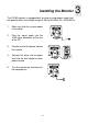
Installing the Monitor 3 The DV180 monitor is equipped with an auto-sensing power supply that will operate within the voltage range of 100 to 240 Volts AC, at 50~60 Hz. 1. Make sure that the system power is turned off. 2. Plug the signal cable into the VGA signal connector at the rear of the PC. 3. Plug the end of the power cord to the monitor. 4. Connect the other end of power cord into the wall socket or other power source. 5. Turn the monitor on and then turn the computer on.
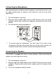
Connecting the Microphone After connecting the microphone to the computer’s sound card, you can use it for video conferencing, to record or edit audio files and for many other applications. 1. Turn the computer system off. 2. Plug one end of audio cable into the LINE IN port at the rear of the computer and the other end to the microphone connector at the rear of the monitor. 3. Turn the monitor and the computer on. ) To record using the microphone, you don't need to be close to the microphone.
) To adjust the audio volume, use the volume control at the right side of your monitor. Connecting Headphones Plug your headphones into the headphone connector at the rear of monitor to avoid disturbing others while still being able to hear audio through the monitor.
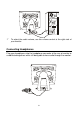
Connecting USB Devices With the Diamond View DV180’s built-in hub, you can easily connect up to 4 USB devices to the computer via the hub. To connect the USB hub to the PC: 1. Turn the system power off. 2. Connect the USB cable to the computer and to the upstream USB port at the rear of monitor. 3. Connect the USB cables of any other peripherals to the downstream USB connectors at the rear of the monitor. 4. Turn the monitor and the computer on.
Setting up and Using the DV180 The Control Panel 4 Adjust. Wheel Auto Power Switch: Turns the monitor on or off. AutoKey: Automatically adjusts the display’s colour temperature, Horizontal Position, Vertical Position, Clock Phase and Pixel Clock. Adj. (Adjust) Wheel: Rotate and press this to access the On Screen Display (OSD).
Automatic Image Adjustment The easiest way to set up the monitor is to display the adjustment test pattern and use the monitor’s AUTO button. The display must be adjusted manually if the test pattern is not available. Please refer to Manual Display Setup on page 18 for details.
Using the On Screen Display The DV180 monitor’s On Screen Display (OSD) allows the brightness, contrast and other image parameters to be easily adjusted for optimum performance. Press the Adjustment (Adj.) wheel once to open the OSD. Menu items are selected by pressing the wheel in once. Turn the wheel to highlight the required menu item and select it to change its setting. Once an item has been selected, turning the wheel downward increases the value of the selected item.
The On Screen Display The On Screen Display (OSD) allows you to adjust the image displayed on the monitor for optimum image clarity and comfortable viewing. A description of the OSD’s menus and their use follows: 1. The Luminance Menu 1. Press the Adjustment wheel to display the main menu. The first function is Luminance. Press the wheel a second time to adjust brightness and contrast. 2. Turn the wheel to highlight the function that is to be adjusted and press the wheel to select it.
2. OSD Icon The Geometry Menu Description Hor. (horizontal) Position Adjusts the horizontal position of the display. Ver. (vertical) Position Adjusts the vertical position of the display. Phase Adjusts the phase of pixel clock. It can improve the focus and stability of your screen as well. Pixel Clock Adjusts the frequency of the pixel. With this function, you can enlarge or reduce the width of your screen. Return Return to last OSD.
3. Colour Adjustment Turn the Adjustment wheel to select the colour that you wish to change. Press the wheel again and turn it to adjust the level of that colour. If you want to and press the wheel. recall a factory preset colour, select OSD Icon Description Factory Default Recall the preset colour settings. Recall R Red level 75 G Green level 75 B Blue level 75 Return Return to last OSD. 4. Recall Factory Settings Select to recall the factory settings.
If you are using a signal with a timing that is not listed on the preset timing table, "Non Preset Mode" will be shown on this page. 5. Miscellaneous OSD Position OSD Icon Description Hor. (horizontal) Position adjusts horizontal position of the OSD. Ver. (vertical) Position adjusts vertical position of the OSD.
ON Enlarges the image to full screen size. If your image already takes up the full screen, this function has no affect. OFF Reduces the screen size. Language Selection Return De: Deutsche En: English Es: Español Fr: Français It: Italiano Ja: Japanese Return to last OSD. 6. Return Return : exits the main menu.
Manual Display Setup The monitor’s display can be manually set up using the Geometry menu. For best performance set the graphics produced by the computer to a resolution of 1280 x 1024 pixels. A refresh rate of 75 Hz is also recommended. The image adjustment is easiest if the test pattern is used. Alternatively, an image with fine text can be used, preferably with black text on a white background. For example, Apple Macintosh users can display the contents of the System folder using the List view.
Supported Graphics Signals and Timings Input Signal from the Computer Dot Clock Resolution Horizontal Vertical Frequency Frequency Frequency (MHz) (Hz) (kHz) 640 x 350 31.47 70.08 25.17 640 x 350 37.86 85.10 31.50 720 x 400 31.47 70.08 28.32 720 x 400 37.93 85.00 35.50 640 x 480 35.00 67.00 30.24 640 x 480 31.47 60.00 25.18 640 x 480 37.86 72.80 31.50 640 x 480 37.50 75.00 31.50 640 x 480 43.27 85.00 36.00 800 x 600 35.16 56.25 36.00 800 x 600 37.88 60.32 40.00 800 x 600 48.08 72.19 50.00 800 x 600 46.
) Signal timings not shown in the table may not be supported. We recommend that you set your graphics card to use one of the factory preset timings to achieve the optimum screen image. ) There are 22 modes that are compatible with VESA standards, Windows 95, 98 and NT, and the Apple Macintosh. ) In some rare cases, the screen may show a small amount of noise. This may be caused by non-standard signal frequencies from the VGA card. It is not a defect.
Troubleshooting and Useful Hints Troubleshooting 6 If you encounter any problems using this product, make sure that your monitor is properly installed. Please refer to chapter 4 of this manual for the installation guide. The answers to some common questions follow: 9 There is some noise or flickering on the screen or the picture is unstable. Check: Signal cable connector pins. If there are bent or missing pins, consult your place of purchase. Graphics card.
9 There is no picture on the screen. Check: Power saving mode. Press any key or move the mouse to deactivate power saving and turn the monitor on. Power cord. Check that it is securely plugged into the wall socket and into the monitor and that the wall socket is switched on. Signal cable connector pins. If there are bent or missing pins, consult your place of purchase. 9 Characters look too dark or too light. Adjust the brightness and contrast settings. 9 The speakers don’t work.
9 The Auto key does not function properly and an "unsupported" message shows. In some non-full-screen patterns, the Auto-key function cannot work properly and an "unsupported" OSD will pop up. In this situation, you need to use the Adjust wheel to set your screen up manually. 9 The sound of speakers distorts and the screen flashes when using speakers. Check whether the audio cable is connected to “ Line Out” port of PC rather than the “Speaker Out” port of the PC’s sound card.
Specifications 7 LCD Panel 18.1” (46 cm) diagonal Active Matrix TFT Maximum Resolution 1280 x 1024 pixels at 75 Hz refresh rate Display Area 359 mm (H) x 287 mm (V) Brightness 235 cd/m² (typical) Contrast Ratio 300:1 Video Input Analogue RGB Horizontal Scanning 31.
Contacting Mitsubishi Electric Australia Address: Mitsubishi Electric Australia Pty. Ltd. 348 Victoria Road, Rydalmere, NSW, 2116 Telephone: (02) 9684-7777 Fax: (02) 9898-0484 Web site: http://www.mitsubishi-electric.com.au Tech. Support: support@meaust.meap.com New Zealand Address: MELCO New Zealand Ltd. 1 Parliament Street, Lower Hutt Telephone: (04) 560-9100 Fax: (04) 560-9140 Web site: http://www.melco.co.