DATA PROJECTOR MODEL XD70U User Manual IMPORTANT * DLP™ (Digital Light Processing) and DMD (Digital Micromirror Device) are registered trademarks of Texas Instruments Incorporated (U.S.A.). * DMD is an ultra-precise part developed by Texas Instruments (U.S.A.) which takes the place of liquid crystal (in the projector). * VGA and XGA are trademarks or registered trademarks of International Business Machines Corporation (U.S.A.). * S-VGA is a registered trademark of Video Electronics Standards Association.
IMPORTANT SAFETY INFORMATION CAUTION RISK OF ELECTRIC SHOCK DO NOT OPEN CAUTION: TO REDUCE THE RISK OF ELECTRIC SHOCK, DO NOT REMOVE COVER (OR BACK) NO USER-SERVICEABLE PARTS INSIDE REFER SERVICING TO QUALIFIED SERVICE PERSONNEL. The lightning flash with arrowhead symbol, within an equilateral triangle, is intended to alert the user to the presence of uninsulated “dangerous voltage” within the product’s enclosure that may be of sufficient magnitude to constitute a risk of electric shock.
IMPORTANT SAFETY INFORMATION CAUTION Do not look at the laser pointer’s light source. Be sure to heed the following. Pointing the laser beam at the eyes could lead to reduced vision or vision impairment. • Never look at the laser pointer’s light source. • Do not point the laser beam at people. • Do not let children use the laser pointer. This label is located on the side of the remote control.
IMPORTANT SAFETY INFORMATION Please read all these instructions regarding your projector and retain them for future reference. Follow all warnings and instructions marked on the projector. 1. Read instructions All the safety and operating instructions should be read before the appliance is operated. 2. Retain instructions The safety and operating instructions should be retained for future reference. 3. Warnings All warnings on the appliance and in the operating instructions should be adhered to. 4.
IMPORTANT SAFETY INFORMATION WARNING: Unplug immediately if there is something wrong with your projector. Do not operate if smoke, strange noise or odor comes out of your projector. It might cause fire or electric shock. In this case, unplug immediately and contact your dealer. Never remove the cabinet. This projector contains high voltage circuitry. An inadvertent contact may result in an electric shock.
Major Features 䡵 Lightweight high-intensity projector The synergy of the DLP™ (Digital Light Processing) display system and our own optical design serve to improve the optical utilization efficiency. The three primary colors (RGB) required in color expression are reproduced with one DMD (Digital Micromirror Device of high precision). These factors have enabled a design that offers both high intensity and small size/ lightweight features.
Table of Contents IMPORTANT SAFETY INFORMATION ................................................................................... E-1 Major Features ....................................................................................................................... E-5 Table of Contents ................................................................................................................... E-6 Checking the Supplied Accessories ..................................................................
Table of Contents Color ...................................................................................................................................... Quick Color Adj. ........................................................................................................ Gamma ..................................................................................................................... Color Temp. ...............................................................................................
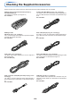
Checking the Supplied Accessories Remove the main unit and the accessories from the box and check that the following items are included. S-Video cable (Mini DIN 4-pin plug, 2 m / 6.6 feet) [1] This cable is used in the connection of video equipment that has an S-video connector. Connections are described on Page E-18. No.
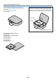
Checking the Supplied Accessories Storage case (for projector and accessories) [1] This case is designed to hold the projector itself and its accessories. Use it when storing the projector. No. 777919700 HOW TO PUT THE PROJECTOR INTO THE STORAGE CASE Close the lens shutter or lens cap before putting the projector in its case, then fasten the projector in place with the Velcro belt. Place the accessories in the storage pocket.
TA TU S N TA S D Y B S TA N D B Y A U TO S O U R C E Names of the Main Unit Parts S Zoom ring [E-24] Focus ring [E-25] Exhaust vents Ventilation slots Remote control sensor [E-13] Adjuster button [E-25] (Also on opposite side) Lens Lens cap Remove before use. Attach the lens cap after use to protect the lens.
Names of the Main Unit Parts STATUS indicator [E-21, 58] STATUS STANDBY indicator [E-21, 58] STANDBY STANDBY button [E-21] STANDBY AUTO button [E-26] AUTO SOURCE button [E-26] SOURCE Remote control sensor [E-13] S TU TA S Y B D N TA S Y B D N TA S TO U A O S E C B R G U R S E ID V O AC IN connector [E-21] O E ID V IO D U A E S U O M PC CO NT RO L Speaker Built-in security slot (See description below.
Names of the Remote Control Parts/Preparing the Remote Control STANDBY button [E-21, 23] This button is used to switch ON the power and set the unit to the STANDBY mode. Buttons used for input selection [E-26] RGB button and VIDEO button (VIDEO / S-VIDEO) Buttons used for menu operations [E-37] The , , and buttons are the select (왖, 왔, 왗 and 왘) buttons.
Names of the Remote Control Parts/Preparing the Remote Control Remote Control Range Point the infrared transmitter of the remote control toward the remote control sensor located at the front or rear of the main unit and operate. Reception of the remote control signal should generally be possible within the range illustrated below. 6m/19.7feet Side View Top View Remote control infrared transmitter et .
The Procedure Up to Projecting to the Screen Perform setup adjustments in the following order. 1 Position the projector Determine the locations to set up the screen and the projector. See “Placement Guide” on Page E-15. 2 Connect the video equipment and personal computer Connect your equipment to the projector. When making connections with the personal computer’s RGB connector, see “Connections with Personal Computer” on Page E-16.
Placement Guide • Use this information as a guide to find out about the screen size when the projector is placed at a certain location, or to find out the approximate size of a screen that will be required. • When suspending the projector from the ceiling, change the projection method. See “Vertical Flip” on E-50. Screen Size and Projection Distance • The projection distance over which focussing is adjustable is 1.20 m (3.94 feet) to 9.59 m (31.46 feet). The projector should be placed within this range.
Connecting Personal Computers and Video Equipment Connecting this unit with a personal computer permits presentation data to be projected as a large screen display at conferences, lectures, and on other occasions. Furthermore, connecting this unit to a DVD player or other video equipment source in combination with an audio/video amplifier and speaker system will allow you to enjoy convincing home theater.
Connecting Personal Computers and Video Equipment To Output the External Output Signal of a Notebook Computer When projection will be with a notebook computer connected, knowledge will be required for the cable connection and notebook computer startup procedure as well as the operation that follows notebook startup. Please consult the instruction manual of your notebook computer or the on-line help while performing the following procedure.
Connecting Personal Computers and Video Equipment Connections with Composite Signals Video Equipment with VIDEO Connectors • The input setting of the VIDEO connector has been set to “Auto” at the factory; however, if the projector does not project, please change the input setting to “Your Country’s Television Broadcast System” using the menu sequence of [Setup] → [Input Format] → [Video]. See “Input Format” on Page E-53.
Connecting Personal Computers and Video Equipment Connections with Component Signals When the Video Equipment Has a YCbCr Connector or YPbPr Connector • The projector has been set to “Auto” at the factory; however, if it does not project, please change the input setting to “Component” using the menu sequence of [Setup] → [Input Format] → [RGB]. See “Input Format” on Page E-53.
Connecting Personal Computers and Video Equipment Connections with the AUDIO Jack * Make the connection to the projector’s AUDIO jack using the supplied audio cable. When the audio jack of the equipment that is to be connected is of the RCA phono type, make connection via the supplied audio conversion cable. * The built-in speaker of the projector provides monaural audio. To enjoy convincing audio reproduction, please connect the audio output of the video equipment to your audio system.
Power Cable Connections and Switching the Power On/Off There is an order in which the power cable is connected and the power is switched on/off. Operating 1 Connect the AC IN connector of the projector and the power outlet using the supplied power cable. The STANDBY indicator will light in amber, and the unit will enter the standby mode.
Power Cable Connections and Switching the Power On/Off When [Menu Language Select] is Displayed Upon Switching On the Power The first time the power is switched on after purchase, [Menu Language Select] will be displayed. Follow the procedure described below and select the display language of the projector. If the image is blurred, turn the focus ring counterclockwise or clockwise to focus it. See Page E-25.
Power Cable Connections and Switching the Power On/Off Finishing 1 Switch off the power of the connected equipment 2 Switch off the power of the projector Press the STANDBY button. STANDBY RGB LASER VIDEO MENU AUTO QUICK Q STANDBY (button on main unit) The [Power Off] display appears. When the level gauge reaches maximum, the projection screen will go off (in about 5 seconds) and the projector will enter the power-off operation.
Adjustment of the Projection Screen Switch on the power of the connected equipment and make the adjustments with the video signal being input to the projector. Adjustment of the Projection Screen 1 Turn the zoom ring to adjust the screen size of the projection image. Adjust the image to match the desired screen size. When outside of the adjustment range, move the projector to the rear or forward. Zoom ring 2 Adjust the projection image to the screen. Check that the screen is set level and vertically.
Adjustment of the Projection Screen 3 Turn the focus ring and adjust the focus of the screen Focus ring XD70 Making Adjustments with the Adjusters TA TU S S TA N D B Y S TA N D B Y A U TO S O U R C E (1) S While viewing the projection image, (1) press and hold the adjuster buttons located at the left and right and, (2) raise the projector to align the image with the screen, then release your fingers. Turn the left and right adjusters for fine adjustment.
General Operation This section describes the use of direct operation with the main unit or remote control buttons. For information about operation using the menu, see “Menu Operation Method” on Page E-37 and the various items on Pages E-44 to E-57. Input Selection This operation selects the input signal to be projected. STANDBY Main unit operation: Press the SOURCE button.
General Operation Selection of Aspect Ratio This function selects horizontal and vertical picture proportions of the input signal. The operations are the same. See E-49 [Aspect]. Personal Computer Signal Auto ............ Automatically enlarges or reduces the image to project a full screen in a ratio of 4:3 Direct .......... Maintains the aspect ratio and projects a picture of the maximum displayable size Real ............
General Operation Freezing a Moving Picture This function is used to stop and view a moving picture. Note that the input image continues to advance even though the picture there is a still picture condition. STANDBY A press of the FREEZE button changes the screen to a still picture. A further press returns the screen to a moving picture.
General Operation Enlargement of the Image and Video Movement This function digitally enlarges the personal computer image and video image. (1) Press the ZOOM button to enlarge the image. The zoom display appears when the ZOOM button is pressed. STANDBY LASER VIDEO RGB AUTO MENU QUICK Q (2) R-CLICK/ CANCEL ENTER Each press of the 왖 button enlarges the image and each press of the 왔 button makes the image smaller (returning it to 1:1).
General Operation Using the Presentation Timer The presentation is given while checking the timer displayed on the screen. The gauge display allows the remaining time to be known at a glance. (1) Press the TIMER button to show the settings display. The display will close when an operation has not been made for about 10 seconds.
General Operation Using the Laser Pointer The remote control unit’s laser pointer can be used to point to the section currently being explained, making presentations more effective. CAUTION Do not look at the laser pointer’s light source. Be sure to heed the following. Pointing the laser beam at the eyes could lead to reduced vision or vision impairment. • Never look at the laser pointer’s light source. • Do not point the laser beam at people. • Do not let children use the laser pointer.
General Operation Performing Mouse Operations on the Computer with the Remote Control Unit When a computer and the projector are connected, mouse operations can be performed on the computer using the projector’s remote control unit. When projecting images from the computer, the projector can be operated and mouse operations on the computer performed with the same remote control unit, making for efficient presentations.
General Operation Controlling the Projector from a Computer Use the control connector if the projector cannot be operated with the remote control unit, for example when it is suspended from the ceiling. Connecting the computer and projector Use a commercially available serial cable (D-Sub 9-pin, straight) to connect the computer’s RS-232C connector to the projector’s control connector (PC CONTROL).
General Operation Protecting the Projector with the Security Lock A password can be registered and the security lock set in order to protect the projector from unauthorized use. Registering the password The password is registered using the menus. For instructions on operating the menus, see “Menu Operations” on E-37. (1) Select “Security Lock” in the “Option” menu and set it to “Enable”. The menu closes and the password registration display appears.
General Operation If the password input display appears when the power is turned on When a password has been registered, the “Password” input window appears on the projected image when the power is turned on. The projector continues projecting this image until the correct password is input. At this time, only the STANDBY button (power off) works. Use the procedure described below to input the registered password. For instructions on registering the password, see E-34.
General Operation Using the Quick Menu This function permits frequently used adjustments to be performed quickly. Note that the Quick Menu will not be displayed unless the signal of the connected equipment is input. Please select the input that you wish to adjust. STANDBY LASER VIDEO RGB AUTO MENU QUICK Q (1) A press of the QUICK MENU button brings up the quick adjustment display. Further presses cause the adjustment display to change in sequence.
Menu Operation Method • This section describes only the menu operation method. Please see this item should you need information while performing menu operations. • For information about a menu function, adjustment, or setting, please see one of the pages containing such descriptions. • Adjustments and settings are made by projecting an image and adjusting to an optimum condition. • The remote control should be pointed toward the remote control sensor of the projector and operated.
Menu Operation Method Menu Screen Names and Functions Menu Name This is the title of the menu. There is a change to the title screen when the menu is selected. The cursor moves to the selected menu name. Cursor (Deep Blue) This permits setting/adjustment of the item located at the cursor position. Item Name This is the name of the adjustment or setting. Icon: Pressing the ENTER button displays the sub menu or setting contents.
Menu Operation Method Performing Menu Operations • Only “Setup”, “Options” and “Info.” can be selected when no signal is being input. • The menu display will close if, after pressing a button, the next button operation is not made within 30 seconds. • The adjustment and the setting values are stored even when the power is switched off or the plug is disconnected from the power outlet. (Note that some items are not stored.
Menu Operation Method Displaying the Cursor 3 Press the 왔 SELECT button to display the item name selection cursor. STANDBY LASER VIDEO RGB AUTO MENU QUICK Q R-CLICK/ CANCEL ENTER FREEZE This condition allows selection of the item name.
Menu Operation Method Closing the Menu 6 Press the MENU button and close the menu display STANDBY RGB LASER VIDEO AUTO QUICK MENU Q R-CLICK/ CANCEL ENTER FREEZE MUTE TIMER Selecting Another Menu Name with Remote Control Operation When a sub menu is displayed, press the CANCEL button and close the sub menu. Press the CANCEL button again to turn off the item name cursor.
Menu Operation Method List of Item Names Offering Input Selection and Adjustments/Settings The item names that can be adjusted/set will differ depending on the input signal. u om t Si gn R pon al G B en t VI D E S- O VI D EO [Example of Menu Display Items at the Time of Input Signal RGB Selection] p Sub Menu Item Name Item Name Image Brightness 嘷 嘷 嘷 嘷 E-44 Contrast 嘷 嘷 嘷 嘷 E-44 嘷 嘷 E-44 嘷 嘷 E-44 嘷 嘷 E-44 In Menu name C Reference Page Color 嘷 Tint Sharpness Picture Adj.
u om t Si gn R pon al G B en t VI D EO SVI D EO Menu Operation Method p Sub Menu Item Name Item Name Setup Auto Source 嘷 嘷 嘷 嘷 E-51 Auto Power Off 嘷 嘷 嘷 嘷 E-51 Memu Position 嘷 嘷 嘷 嘷 E-52 Lamp Mode 嘷 嘷 嘷 嘷 E-52 RGB 嘷 嘷 嘷 嘷 E-53 Video 嘷 嘷 嘷 嘷 E-53 S-Video 嘷 嘷 嘷 嘷 E-53 Presentation Timer 嘷 嘷 嘷 嘷 E-53 Language 嘷 嘷 嘷 嘷 E-54 On Screen 嘷 嘷 嘷 嘷 E-54 Background 嘷 嘷 嘷 嘷 E-54 Startup Screen 嘷 嘷 嘷 嘷 E-55 Security Lock 嘷 嘷 嘷 嘷 E-55 Statu
Image • Perform this operation while projecting the picture for which the adjustment/setting will be made. • Select the menu name “Image”. See “Menu Operation Method” on Page E-37 for information about performing menu operations. The item name display will differ depending on the input signal. See “List of Item Names Offering Input Selection and Adjustments/Settings” on Page E-42.
Image Fine Picture Adjust this when the picture shows a lack of color fidelity or flickering. Select the “Fine Picture” item name and adjust with the SELECT 왗왘 buttons so that the lack of color fidelity or the flickering disappears. H Position Adjust this when the picture is shifted to the left or right. Select the “H Position” item name and adjust with the SELECT 왗왘 buttons. V Position Adjust this when the picture is shifted up or down.
Color • Do the following operation while displaying the image you want to adjust or set. • Select the menu name “Color”. See “Menu Operation Method” on Page E-37 for information about performing menu operations. The item name display will differ depending on the input signal. See “List of Item Names Offering Input Selection and Adjustments/Settings” on Pages E42. Quick Color Adj. Select the preset color mode. Select the “Quick Color Adj.
Color Color Temp. The screen color is affected by the color of the illumination and other extraneous light. This function adjusts the white, which is the reference color for video equipment, and improves the quality of color reproduction. Adjustment can also be used to enhance skin colors. Select the item name “Color Temp.” and select the setting contents with the SELECT 왗왘 buttons. Low ............ Medium ...... Normal ....... High ............
Color White Balance This function automatically adjusts the black level and the white level of the analog RGB input signal to suit the personal computer. 1 Select the item name [White Balance] and press the ENTER button. The display will change to [Input Black Signal]. 2 The screen background color of the connected personal computer will be set to black. 3. Press the ENTER button. The display will change to [Adjusting Black] and the black level will be adjusted.
View • Perform this operation while projecting the picture for which the adjustment/setting will be made. • Select the menu name “View”. See “Menu Operation Method” on Page E-37 for information about performing menu operations. The item name display will differ depending on the input signal. See “List of Item Names Offering Input Selection and Adjustments/Settings” on Page E-42. Aspect This function sets the horizontal and vertical picture proportions of the input signal.
View Vertical Flip/Horizontal Flip In selecting the method of projecting to the screen, these functions are set when the projector is in a suspended or a rear screen installation. XD70 XD70 Select the item name “Vertical Flip” or “Horizontal Flip” and select the setting contents with the SELECT 왗왘 buttons.
Setup • Select menu name “Setup”. See “Menu Operation Method” on Page E-37 for information about performing menu operations. The item name display will differ depending on the input signal. See “List of Item Names Offering Input Selection and Adjustments/Settings” on Page E-42. Auto Source The Auto Source function automatically detects the input signal when the power supply is switched on and when the input is switched.
Setup Menu Position This function sets the display position of the menu. Select item name “Menu Position” and select the setting contents with the SELECT 왗왘 buttons. ............. Displays on the left side ............. Displays on the right side Lamp Mode Use this if the picture is projected on a small screen and the picture is too bright or when projecting images in dark rooms. Select the item name “Lamp Mode” and select the setting contents with the SELECT 왗왘 buttons. Low ............
Setup Input Format This function is used in setting the input signals of the input connectors. Normally, this should be set to Auto. When identification is not possible with Auto, make the setting. Select the item name “Input Format”, press the ENTER button, and the sub menu will open. Select the connector that is to be changed, and select the setting contents with the SELECT 왗왘 buttons. [RGB] This is the signal setting for the RGB connector. Auto ............ Automatically identifies the signal. RGB .....
Option • Select menu name “Option”. See “Menu Operation Method” on Page E-37 for information about performing menu operations. The item name display will differ depending on the input signal. See “List of Item Names Offering Input Selection and Adjustments/Settings” on Page E-42. Language This function sets the language that is displayed on screen in the messages and menu displays. Select item name “Language” and press the ENTER button to open the Language sub menu.
Option Startup Screen This is the selection of whether or not to display the logo screen at startup time. Select item name “Startup Screen” and select the setting contents with the SELECT 왗왘 buttons. Logo ........... Displays the logo. Blank .......... Does not display the logo. Note: When “Logo” is selected at the startup screen, the “PROJECTOR XD70” logo is displayed. Security Lock A password can be registered and the security lock set in order to prevent unauthorized use of the projector.
Info. • Select menu name “Info.”. See “Menu Operation Method” on Page E-37 for information about performing menu operations. The item name display will differ depending on the input signal. See “List of Item Names Offering Input Selection and Adjustments/Settings” on Page E-42. Status This displays information about the equipment. Select item name “Status” and press the ENTER button. There is a change to the status display. Press the CANCEL button to return to the menu.
Info. Resolution / Frequency This function displays the resolution and frequency of the detected input signal. Lamp Timer This displays the lamp timer. This projector has an Low mode function. The lamp life will differ between Normal mode and Low mode. Lamp Life Use only in Normal mode: approx.2000 hours Use only in Low mode: approx.3000 hours * Lamp life will differ when there has been switching between the modes.
When an Indicator is Lit or Flashing The indicators on the projector’s control panel light or flash to notify of problems, as described below. An indicator is also used to notify you of the currently set power mode (under normal circumstances). See “Power Cable Connections and Switching the Power On/Off” on page E-21.
Troubleshooting Check the following matters before requesting servicing. Problem Power does not turn on Reference Page Check • Is the power cord plugged into a power outlet? • Is the lamp cover properly mounted? • Is the projector’s temperature high? To protect the projector, the power cannot be turned on when the projector’s temperature is abnormally high.
Cleaning • Be certain to disconnect the power plug from the power outlet before cleaning. • Do not spray or otherwise expose the projector, lens, or screen to volatile substances such as insecticides. Do not leave rubber or vinyl products in contact with the projector for long periods. Doing so could cause them to undergo qualitative changes or the coatings may peel, etc. Cleaning a Soiled Projector Main Unit • Wipe with a lint-free, soft, dry cloth.
Replacing the Lamp Cartridge • The lamp that is used as a light source in the projector has a limited service life. The rated service life of the lamp is about 2000 hours (when used in normal mode only). This could be shortened depending on conditions of use and other factors. Note that lamp life will be extended when the projector is often used in Low mode.
Replacing the Lamp Cartridge Preparations: Turning the projector upside-down on top of a soft cloth, etc., so that it does not get scratched makes it easier to replace the lamp cartridge. Turn the projector right-side up after replacing the lamp cartridge. 1 Unplug the power cord. 2 Turn the projector upside-down. 3 Remove the lamp cover. (1) Turn the lamp cover’s set screw counterclockwise and loosen until the screw turns freely. (The screw does not come off.
Replacing the Lamp Cartridge 5 Mount the new lamp cartridge. (1) Push the lamp cartridge in slowly. (Line it up with the screw holes in the projector.) (2) Turn the lamp cartridge screw clockwise to tighten them. 6 Mount the lamp cover. (1) Set the tip of the lamp cover in place, then close the lamp cover. (2) Turn the lamp cover’s screw clockwise to tighten it. 7 Reset the Lamp Timer. Connect the power cable, switch on the power, and then reset. Select [Info.
Specifications Model XD70U Optical Method of projection : DMD Lamp Projection lens : Image size Light Output Contrast Ratio DLP™ (single chip DMD) 0.7 inches 1024⳯768 dots 200 W high pressure mercury lamp Manual zoom (⳯1.2), Manual focus F = 2.6 – 2.9, f = 18.4 – 22.1 mm (f = 0.72 – 0.87 inch) Minimum: 38.4 inch (at projection distance of 1.2m(3.9 feet) telephoto) Maximum: 300 inch (at projection distance of 8.0m(26.
Table of Supported Frequency The projector automatically identifies the signal input from the computer and selects the optimum resolution as shown on the table below. Manual adjustments may be required for some input signals. See “Picture Adj. / Fine Picture / H Position / V Position” on page E44, 45.
Cabinet Dimensions SOURCE AUTO STANDBY STANDBY 252 (9.9) STATUS 60 (2.4) 216 (8.
MITSUBISHI ELECTRIC CORPORATION 1 Zusho Baba, Nagaokakyo-City, Kyoto Japan