
User manual

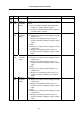


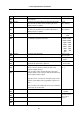


Table Of Contents
- Cover
- Introduction
- Precautions for Safety
- CONTENTS
- 1. Parameter Screens
- 2. Machining Parameters
- 3. I/O Parameters
- 4. Setup Parameters
- 5. Base Specifications Parameters
- 6. Axis Specifications Parameters
- 7. Servo Parameters
- 8. Spindle Parameters
- 9. Machine Error Compensation
- 10. PLC Constants
- 11. Macro List
- 12. Position Switch
- 13. Indexing Axis Parameters
- 14. Indexing Axis Position Switch
- 15. Indexing Axis Commands
- 16. Auxiliary Axis Parameters
- Revision History
- Back cover
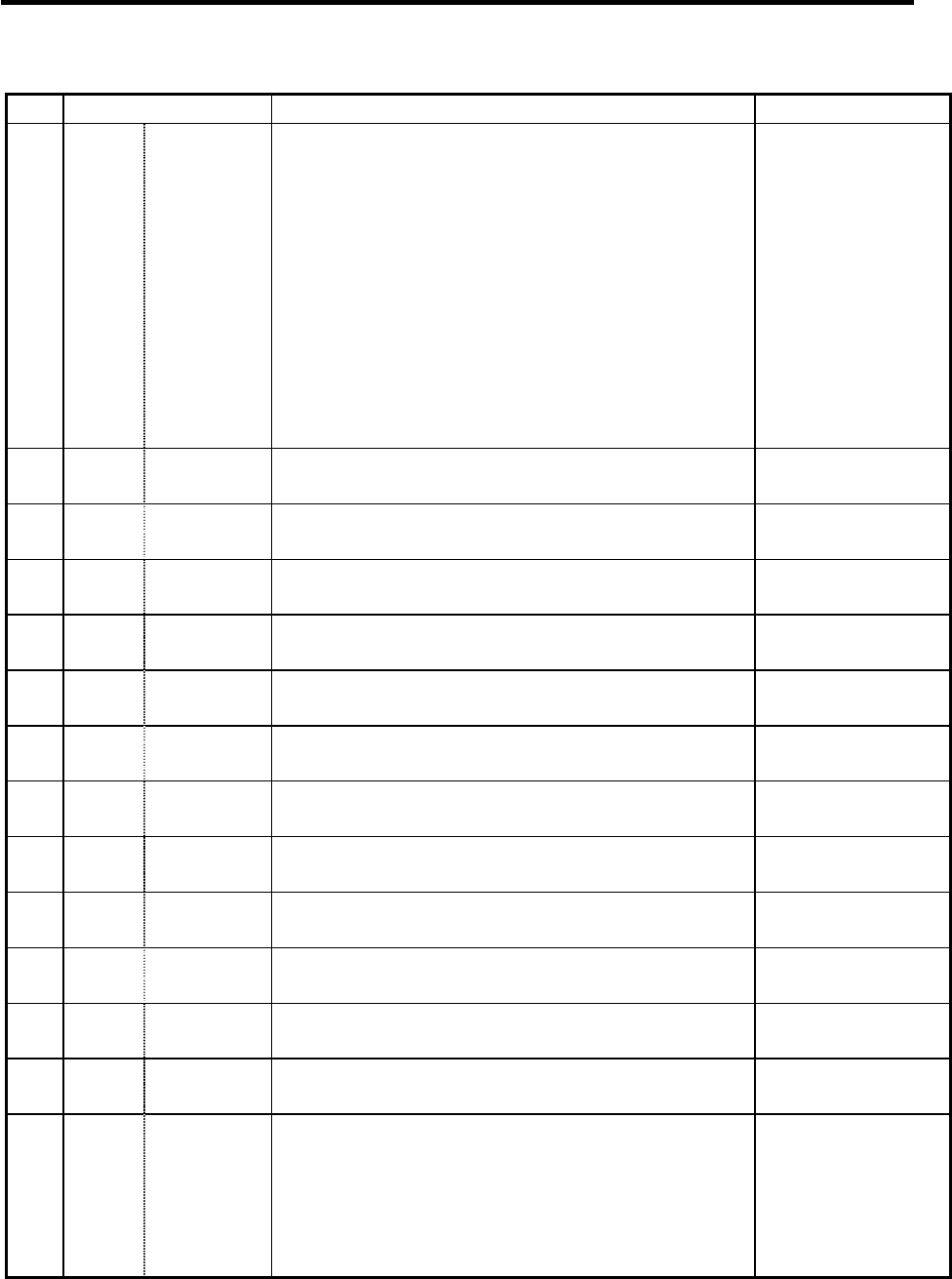
5. Base Specifications Parameters
57
# Items Details
Setting range (unit)
ext23
(bit7)
Absolute
coordinate
display
(M system)
0: Displays the actual position including tool radius
compensation.
1: Displays the machining position in terms of a
program command excluding tool radius compen-
sation.
(L system)
0: Displays the actual position including nose R
compensation.
1: Displays the machining position in terms of a
program command excluding nose R compen-
sation.
0/1
1288
(PR)
ext24 Not used.
1289
(PR)
ext25 Not used.
1290
(PR)
ext26 Not used.
1291
(PR)
ext27 Not used.
1292
(PR)
ext28 Not used.
1293
(PR)
ext29 Not used.
1294
(PR)
ext30 Not used.
1295
(PR)
ext31 Not used.
1296
(PR)
ext32 Not used.
1297
(PR)
ext33 Not used.
1298
(PR)
ext34 Not used.
1299
(PR)
ext35 Not used.
1300
(PR)
ext36
(bit7)
Spindle
synchro-
nization
command
method
Select the command method for spindle synchronous
control.
0: Spindle synchronous control II
(Controlled by PLC I/F)
1: Spindle synchronous control I
(Controlled by G code)
0/1