
User manual


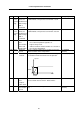

Table Of Contents
- Cover
- Introduction
- Precautions for Safety
- CONTENTS
- 1. Parameter Screens
- 2. Machining Parameters
- 3. I/O Parameters
- 4. Setup Parameters
- 5. Base Specifications Parameters
- 6. Axis Specifications Parameters
- 7. Servo Parameters
- 8. Spindle Parameters
- 9. Machine Error Compensation
- 10. PLC Constants
- 11. Macro List
- 12. Position Switch
- 13. Indexing Axis Parameters
- 14. Indexing Axis Position Switch
- 15. Indexing Axis Commands
- 16. Auxiliary Axis Parameters
- Revision History
- Back cover
5. Base Specifications Parameters
44
# Items Details
Setting range (unit)
aux03
(bit7)
Time
constant
setting
changeover
for software
acceleration/
deceleration
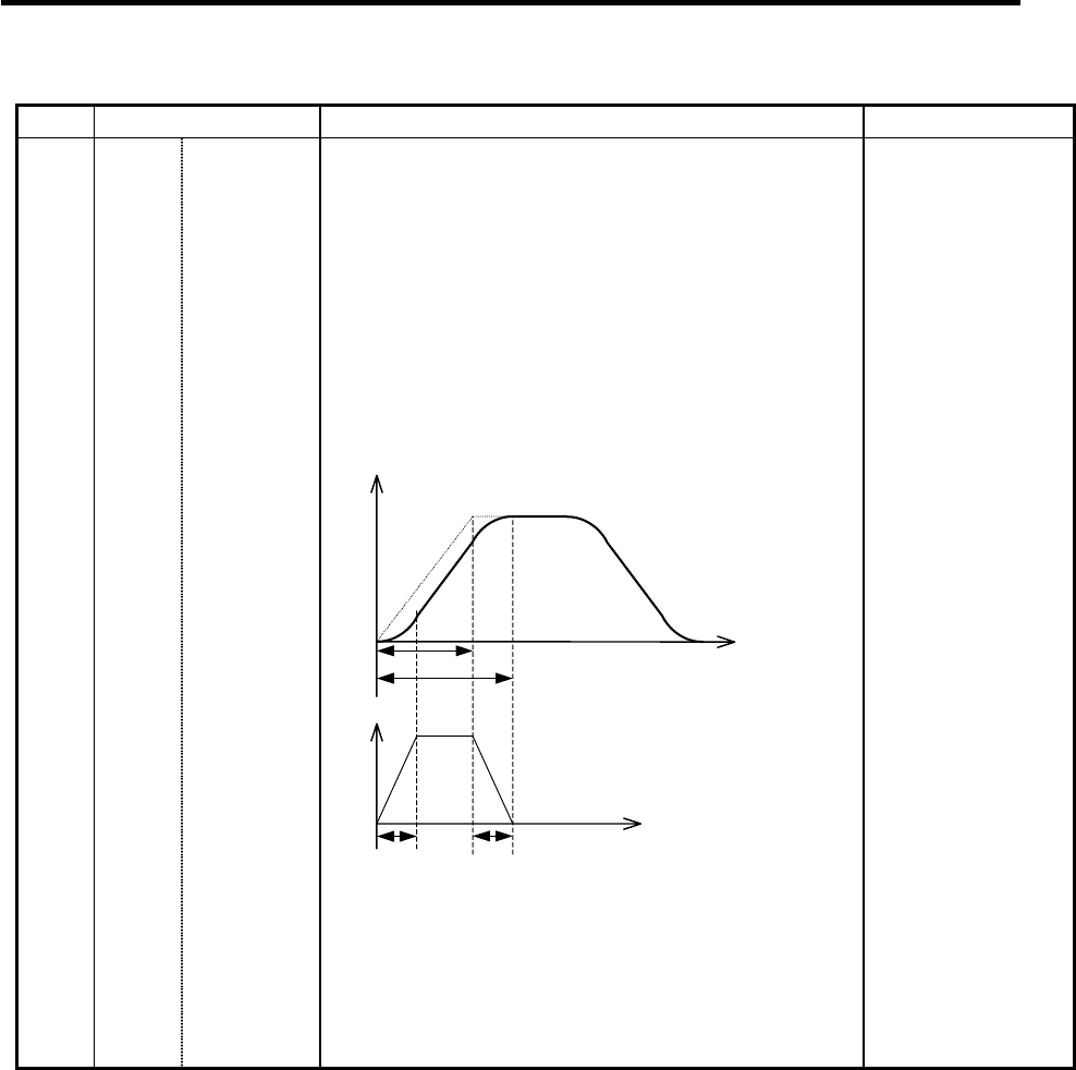
0: Accelerating time is G0tL(G1tL).
If the time is set to the software
acceleration/deceleration 2nd step time constant
(#2005 G0t1) under such condition as the
acceleration/deceleration before G00 interpolation
and the software acceleration/deceleration are
used one together, the inclination at software
acceleration/deceleration will be steeper.
Thus, the acceleration for G28/G30 will be larger
than that for G00.
G0tl
G0tL-G0tl
G0tL
G0tl
Speed
A
cceleration
t
t
1. Total accelerating time is “G0L”.
2. The time for curve part is “G0t1”.
3. The time for linear part is obtained by
“G0tL-(2UG0t1)”.
(Continued on the next page)
0/1