
User manual


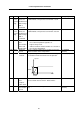

Table Of Contents
- Cover
- Introduction
- Precautions for Safety
- CONTENTS
- 1. Parameter Screens
- 2. Machining Parameters
- 3. I/O Parameters
- 4. Setup Parameters
- 5. Base Specifications Parameters
- 6. Axis Specifications Parameters
- 7. Servo Parameters
- 8. Spindle Parameters
- 9. Machine Error Compensation
- 10. PLC Constants
- 11. Macro List
- 12. Position Switch
- 13. Indexing Axis Parameters
- 14. Indexing Axis Position Switch
- 15. Indexing Axis Commands
- 16. Auxiliary Axis Parameters
- Revision History
- Back cover
5. Base Specifications Parameters
40
# Items Details
Setting range (unit)
1203 TmirS1
(For L
system
only)
Select
turrets for
double-turret
mirror image
with T
command
Set up turrets for double-turret mirror image with the T
command that corresponds to tool numbers 1 to 32.
0 to FFFFFFFF
1204 TmirS2
(For L
system
only)
Select
turrets for
double-turret
mirror image
with T
command
Set up turrets for double-turret mirror image with the T
command that corresponds to tool numbers 33 to 64.
0 to FFFFFFFF
1205 G0bdcc Acceleration
and
deceleration
before G0
interpolation
0: G00 acceleration and deceleration are selected as
those after interpolation regardless of
high-accuracy mode.
1: G00 acceleration and deceleration are selected as
those before interpolation.
0/1
1206 G1bF Maximum
speed
Set up a cutting feedrate when selecting acceleration
and deceleration before interpolation.
1 to 1000000
(mm/min)
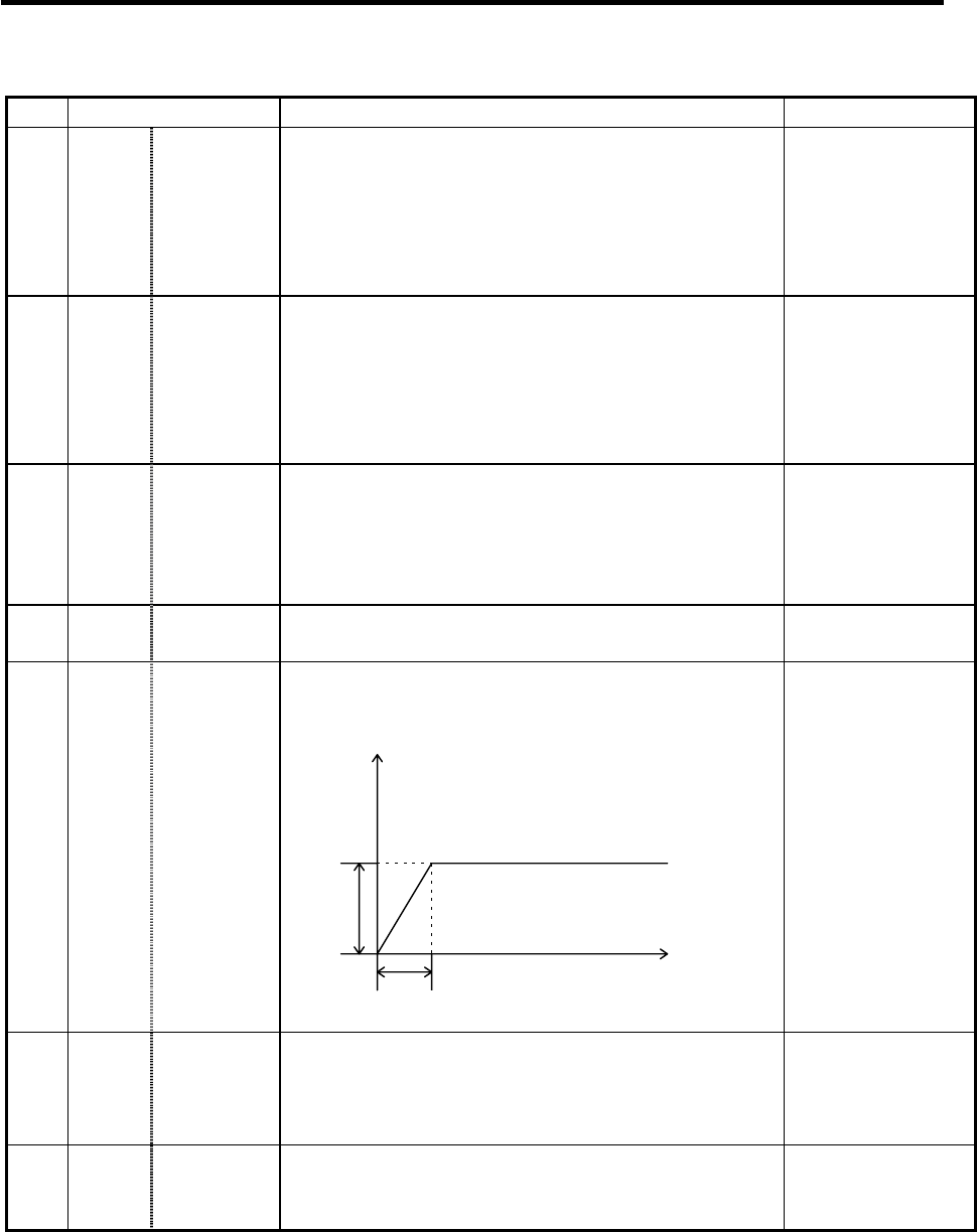
1207 G1btL Time
constant
Set up a cutting feed time constant when selecting
acceleration and deceleration before interpolation.
Speed
Time
G1bF
G1btL
1 to 5000 (ms)
1208 RCK Arc radius
error
compen-
sation factor
An arc radius error compensation amount can be
increased and decreased from −60.0 to 20.0%.
−60.0 to +20.0 (%)
1209 cirdcc Arc
deceleration
speed
Specify the deceleration speed at the arc entrance or
exit.
1 to 1000000
(mm/min)