
User manual

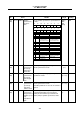

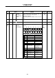


Table Of Contents
- Cover
- Introduction
- Precautions for Safety
- CONTENTS
- 1. Parameter Screens
- 2. Machining Parameters
- 3. I/O Parameters
- 4. Setup Parameters
- 5. Base Specifications Parameters
- 6. Axis Specifications Parameters
- 7. Servo Parameters
- 8. Spindle Parameters
- 9. Machine Error Compensation
- 10. PLC Constants
- 11. Macro List
- 12. Position Switch
- 13. Indexing Axis Parameters
- 14. Indexing Axis Position Switch
- 15. Indexing Axis Commands
- 16. Auxiliary Axis Parameters
- Revision History
- Back cover

8. Spindle Parameters
8.4 MDS-C1-SPM
258
No. Items Details
Setting
range
Standard
setting
3390 SP190 PG3S Spindle
synchronous
Position loop
gain 3
Set the third position loop gain when high-gain
control is carried out in the spindle
synchronous mode.
When this parameter function is not used, set
to "0".
0 to 999
(1/s)
0
3391
SP191 Use not possible. 0 0
3392
SP192 Not used. Set to "0".
3393
(PR)
SP193 SPECT Synchronized
tapping
specifications
Set the synchronized tapping specifications in
bit units.
0000 to
FFFF
HEX
setting
0000
F E D C B A 9 8
zrtn ptyp od8x phos
7 6 5 4 3 2 1 0
fdir cdir pyfx rtrn fclx
bit Name Meaning when set to 0 Meaning when set to 1
0
fclx Closed loop Semi-closed loop
(Gear 1 : 1 only)
1
2
rtrn Position monitor during
ready OFF invalid
Position monitor during
ready OFF valid
3
4 cdir Command polarity (+) Command polarity (–)
5
fdir Position detector
polarity (+)
Position detector
polarity (–)
6
7
8
phos Normal
(no compensation)
Synchronized tapping
position command
compensation
(for synchronization with
high-gain servo)
9
A
B
C
D
od8x Magnification of
excessive error width ×
8 times invalid
Magnification of
excessive error width ×
8 times valid
E
ptyp Position control switch
type: After zero point
return
Position control switch
type: After deceleration
stop
F
zrtn Zero point return
direction: CCW
Zero point return
direction: CW