
User manual


Table Of Contents
- Cover
- Introduction
- Precautions for Safety
- CONTENTS
- 1. Parameter Screens
- 2. Machining Parameters
- 3. I/O Parameters
- 4. Setup Parameters
- 5. Base Specifications Parameters
- 6. Axis Specifications Parameters
- 7. Servo Parameters
- 8. Spindle Parameters
- 9. Machine Error Compensation
- 10. PLC Constants
- 11. Macro List
- 12. Position Switch
- 13. Indexing Axis Parameters
- 14. Indexing Axis Position Switch
- 15. Indexing Axis Commands
- 16. Auxiliary Axis Parameters
- Revision History
- Back cover
8. Spindle Parameters
8.4 MDS-C1-SPM
239
No. Items Details
Setting
range
Standard
setting
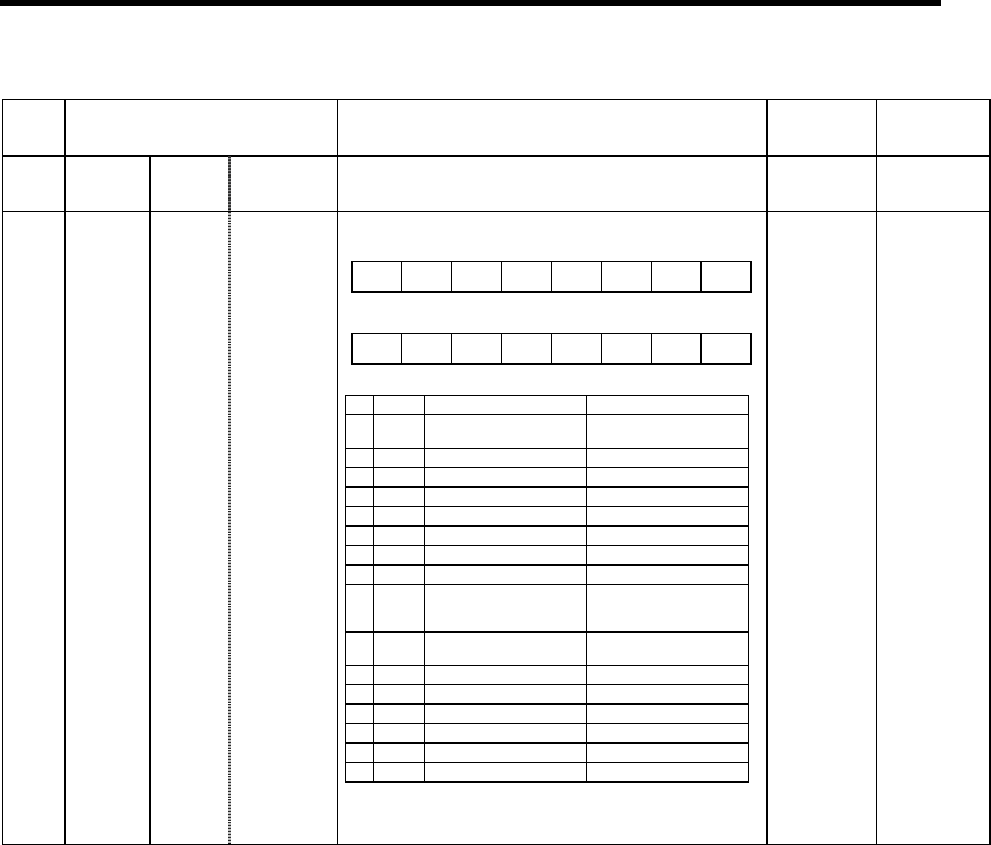
3236
SP036 Not used. Set to "0".
3237
(PR)
SP037 SFNC5 Spindle
function 5
Set the spindle function 5 in bit units.
0000 to
FFFF
HEX
setting
0000
F E D C B A 9 8
nsno nosg
7 6 5 4 3 2 1 0
plgo enco
(Note) Always set "0" for the empty bits.
bit Name Meaning when set to 0 Meaning when set to 1
0
enco Encoder orientation
invalid
Encoder orientation
valid
1
2 plgo PLG orientation invalid PLG orientation valid
3
4
5
6
7
8
nosg No-signal detection type
(Always monitoring)
Monitoring only in
position loop or
orientation-mode
9 nsno
No-signal detection
valid
No-signal detection
invalid
A
B
C
D
E
F
(Note) For bit0 to 2, do not set two bits or more to
"1" at the same time.