
User manual


Table Of Contents
- Cover
- Introduction
- Precautions for Safety
- CONTENTS
- 1. Parameter Screens
- 2. Machining Parameters
- 3. I/O Parameters
- 4. Setup Parameters
- 5. Base Specifications Parameters
- 6. Axis Specifications Parameters
- 7. Servo Parameters
- 8. Spindle Parameters
- 9. Machine Error Compensation
- 10. PLC Constants
- 11. Macro List
- 12. Position Switch
- 13. Indexing Axis Parameters
- 14. Indexing Axis Position Switch
- 15. Indexing Axis Commands
- 16. Auxiliary Axis Parameters
- Revision History
- Back cover
7. Servo Parameters
7.4 Supplement
171
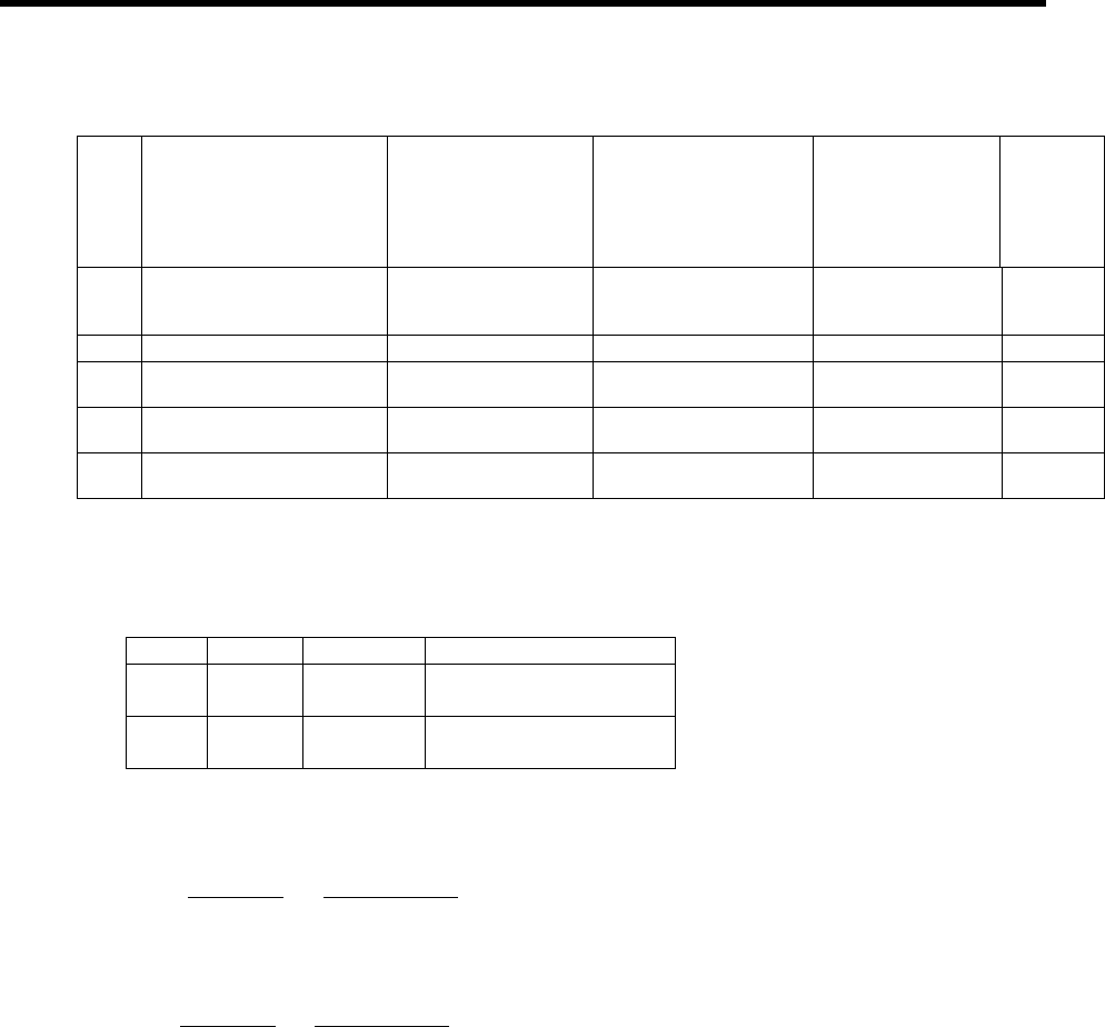
(Continued from the previous page)
No. Output data
Standard output
unit
Standard setting
value of output
scale
(Setting values in
SV063, SV064)
Standard
output unit
Output
cycle
77
Estimated disturbance
torque
Internal unit
8
(adjustment
required)
– 888µs
125
Saw-tooth wave test
output
0V to 5V 0 (256) Cycle: 227.5ms 888µs
126
Rectangular wave test
output
0V to 5V 0 (256) Cycle: 1.7ms 888µs
127
2.5V (data 0) test
output
2.5V 0 (256) – 888µs
(c) Setting the output scale
# No. Abbrev Parameter name
2263 SV063 DA1MPY D/A output channel 1
output scale
2264 SV064 DA2MPY D/A output channel 2
output scale
Usually, the standard setting value is set for the output scale (SV063, SV 064). When “0” is set,
the output will be made as well as when “256” is set.
SV063 5 [V]
DATA x
256
x
256 (8bit)
+ 2.5 [V] (offset) = Output voltage [V]
(Example) When outputting the current FB with 100%/V–stall (SV061=3, SV063=131)
131 5
100 x
256
x
256
+ 2.5 = 3.499 [V]