
User's Manual


Quick Start Guide
6 Set Up the Hardware
Issue 02 (2014-04-29)
8
LED name
Location
Color
LED
Behavior
Status Indication
Table 6-1 Signal Strength LED Definition
RSRP: dBm
SINR: dB
RSRP <
-114
-114 <=
RSRP<
-109
-109 <=
RSRP<
-104
-104 <=
RSRP <
-94
-94 <=
RSRP <
-84
RSRP >
= -84
SINR < -2.8
0
1
1
1
1
1
-2.8 <= SINR <
1.2
0
1
2
2
2
2
1.2 <= SINR <
4.8
0
1
2
3
3
3
4.8 <= SINR <
13.2
0
1
2
3
4
4
SINR >= 13.2
0
1
2
3
4
5
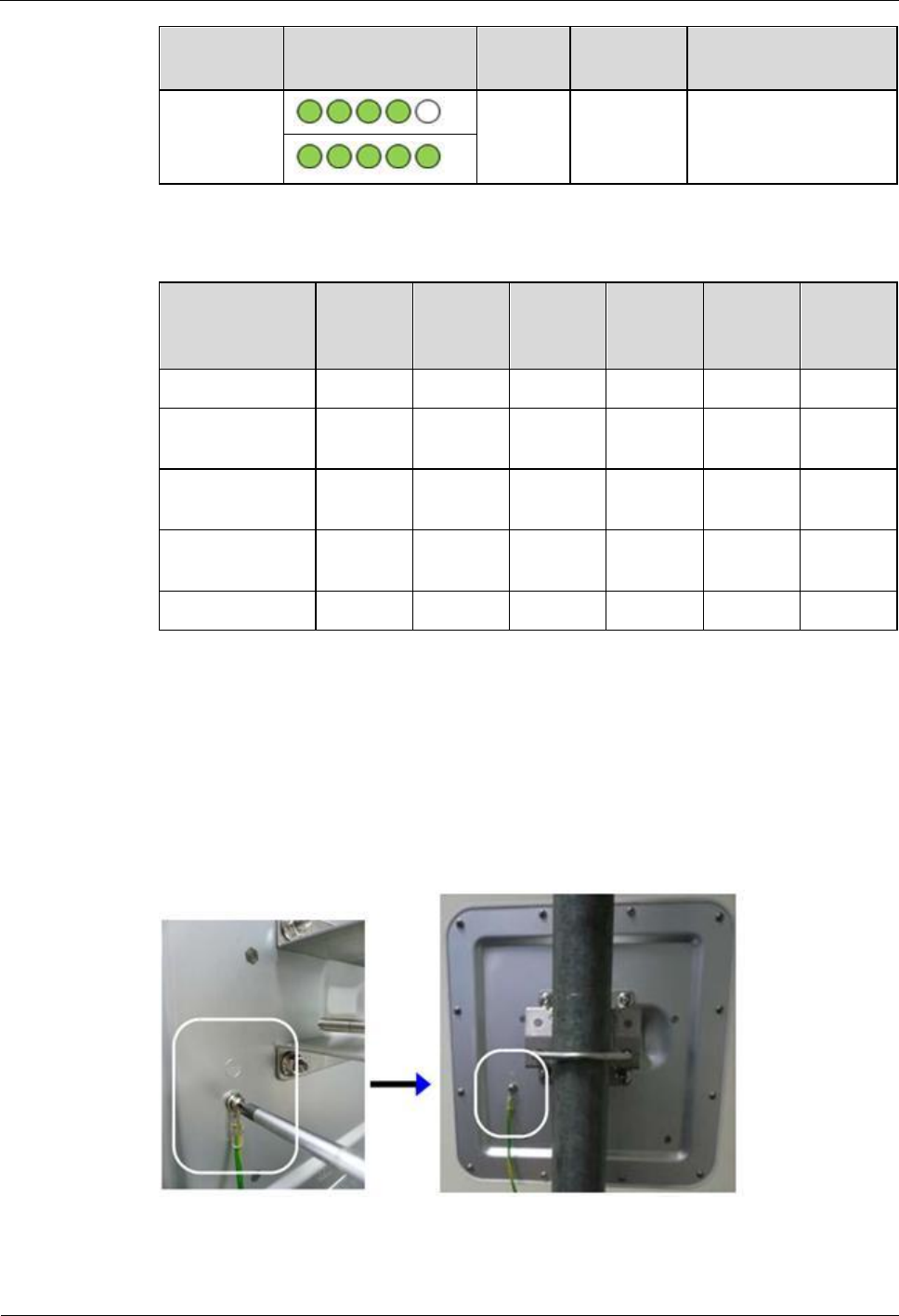
6.4 Grounding
Step 1 Use the M4 screw to connect the ground cable to the ground hole on the LTE Device's rear
panel as shown.
Figure 6-2 Attach the Ground Cable to the ODU
Step 2 Attach the other endof theground cable to a wallor theground.