HES-209M1H BM2022 WiMAX IEEE 802.16 Indoor CPE Default Login Details IP Address: http://192.168.1.1 Username admin Password 1234 Firmware Version V2.00 Edition 1, 4/2011 www.huawei.com Copyright 2011 Huawei Technologies Co., LTD.
About This User's Guide About This User's Guide Intended Audience This manual is intended for people who want to configure the Huawei BM2022 using the Huawei Web Configurator. You should have at least a basic knowledge of TCP/IP networking concepts and topology. Related Documentation Quick Start Guide The Quick Start Guide is designed to help you get up and running right away. It contains information on setting up your network and configuring for Internet access.
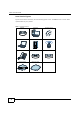
About This User's Guide Icons Used in Figures Figures in this User s Guide may use the following generic icons. The BM2022 icon is not an exact representation of your product.
Safety Warnings Safety Warnings For your safety, be sure to read and follow all warning notices and instructions. Do NOT use this product near water, for example, in a wet basement or near a swimming pool. Do NOT expose your device to dampness, dust or corrosive liquids. Do NOT store things on the device. Do NOT install, use, or service this device during a thunderstorm. There is a remote risk of electric shock from lightning. Connect ONLY suitable accessories to the device.
Contents Overview Contents Overview User s Guide ........................................................................................................................... 15 Getting Started ...........................................................................................................................17 Introducing the Web Configurator ..............................................................................................21 Setup Wizard...................................................
Contents Contents About This User's Guide .......................................................................................................... 3 Safety Warnings........................................................................................................................ 5 Contents Overview .................................................................................................................. 7 Contents ..............................................................................
Contents Chapter 4 Tutorials ................................................................................................................................... 35 4.1 Overview ..............................................................................................................................35 4.2 WiMAX Connection Settings ................................................................................................35 4.3 Configuring LAN DHCP ...................................................
Contents 6.9 Connect ................................................................................................................................81 6.10 Wide Scan ..........................................................................................................................84 6.11 Link Status ..........................................................................................................................86 6.12 Link Statistics ........................................................
Contents 8.5 PPTP VPN Server ..............................................................................................................125 8.6 PPTP VPN Client ...............................................................................................................127 8.7 PPTP VPN Client: Add .......................................................................................................127 8.8 L2TP VPN Server .................................................................................
Contents 10.7 FAX ..................................................................................................................................163 10.8 Technical Reference .........................................................................................................163 10.8.1 SIP Call Progression with Session Timer ...............................................................163 10.8.2 SIP Client Server ......................................................................................
Contents 13.1 Power, Hardware Connections, and LEDs .......................................................................193 13.2 BM2022 Access and Login ..............................................................................................194 13.3 Internet Access ................................................................................................................195 13.4 Reset the BM2022 to Its Factory Defaults .......................................................................
P ART I User s Guide 15
C HAPTER 1 Getting Started 1.1 About Your BM2022 The BM2022 allows you to access the Internet by connecting to a WiMAX wireless network. You can use a traditional analog telephone to make Internet calls using the BM2022 s Voice over IP (VoIP) communication capabilities. Additionally, The web browser-based Graphical User Interface (GUI), also known as the web configurator, provides easy management of the device and its features. See Chapter 14 on page 199 for a complete list of features for your model. 1.
Chapter 1 Getting Started 1.1.2 Make Calls via Internet Telephony Service Provider In a home or small office environment, you can use the BM2022 to make and receive the following type of VoIP telephone calls: Calls via a VoIP service provider - The BM2022 sends your call to a VoIP service provider s SIP server which forwards your calls to either VoIP or PSTN phones. Figure 2 Calls via VoIP Service Provider 1.
Chapter 1 Getting Started 1.2.1 LEDs The following figure shows the LEDs (lights) on the BM2022. Figure 3 The BM2022 s LEDs POWER LED WIMAX LINK SIGNAL STRENGTH INDICATORS VOICE LED The following table describes your BM2022 s LEDs (from top to bottom). Table 2 The BM2022 LEDs behavior LED STATE DESCRIPTION Power Off The BM2022 is not receiving power. Red The BM2022 is receiving power but has been unable to start up correctly or is not receiving enough power.
Chapter 1 Getting Started Table 2 The BM2022 LEDs behavior LED STATE DESCRIPTION Voice Off No SIP account is registered, or the BM2022 is not receiving power. Green A SIP account is registered. Green (Blinking) A SIP account is registered, and the phone attached to the VoIP port is in use (off the hook). Yellow A SIP account is registered and has a voice message on the SIP server.
C HAPTER 2 Introducing the Web Configurator 2.1 Overview The Web Configurator is an HTML-based management interface that allows easy device set up and management via any web browser that supports: HTML 4.0, CSS 2.0, and JavaScript 1.5, and higher. The recommended screen resolution for using the web configurator is 1024 by 768 pixels and 16-bit color, or higher. In order to use the Web Configurator you need to allow: Web browser pop-up windows from your device.
Chapter 2 Introducing the Web Configurator 2.1.2 The Reset Button If you forget your password or cannot access the Web Configurator, you will need to use the Reset button to reload the factory-default configuration file. This means that you will lose all configurations that you had previously and the password will be reset to 1234 . 2.1.2.1 Using The Reset Button 1 Make sure the Power light is on (not blinking).
Chapter 2 Introducing the Web Configurator 2.1.4 Working with Tables Many screens in the BM2022 contain tables to provide information or additional configuration options. Figure 6 Tables Example This screen contains the following fields: Table 4 Saving and Canceling Changes LABEL DESCRIPTION Items per Page This displays the number of items displayed per table page. Use the menu to change this value. First Page Click this to go to the first page in the table.
Chapter 2 Introducing the Web Configurator Figure 7 Main Screen The following table describes the icons in this screen. Table 5 Main > Icons ICON DESCRIPTION System Status Click this to open the Main screen, which shows your BM2022 status and other information. WiMAX Click this to open the WiMAX menu, which gives you options for configuring your WiMAX settings. Network Setting Click this to open the Network menu, which gives you options for configuring your network settings.
Chapter 2 Introducing the Web Configurator Table 5 Main > Icons (continued) ICON DESCRIPTION Maintenance Click this to open the Maintenance menu, which gives you options for maintaining your BM2022 and performing basic network connectivity tests. Language Use this menu to select the Web Configurator s language. Setup Wizard Click this to open the Setup Wizard, where you can configure the most essential settings for your BM2022 to work. Logout Click this to log out of the Web Configurator.
Chapter 2 Introducing the Web Configurator 26 BM2022 User s Guide
C HAPTER 3 Setup Wizard 3.1 Overview This chapter provides information on the Huawei Setup Wizard. The wizard guides you through several steps for configuring your network settings. 3.1.1 Welcome to the Setup Wizard This screen provides a quick summary of the configuration tasks the wizard helps you to perform. They are: 1 Set up your Local Area Network (LAN) options, which determine how the devices in your home or office connect to the BM2022.
Chapter 3 Setup Wizard 3.1.2 LAN Settings The LAN Settings screen allows you to configure your local network options. Figure 9 Setup Wizard > LAN Settings The following table describes the labels in this screen. Table 6 Setup Wizard > LAN Settings LABEL DESCRIPTION LAN TCP/IP IP Address Enter the IP address of the BM2022 on the LAN. Note: This field is the IP address you use to access the BM2022 on the LAN.
Chapter 3 Setup Wizard Table 6 Setup Wizard > LAN Settings (continued) LABEL DESCRIPTION Second DNS Server Specify the second IP address of three DNS servers that the network can use. The BM2022 provides these IP addresses to DHCP clients. Third DNS Server Specify the third IP address of three DNS servers that the network can use. The BM2022 provides these IP addresses to DHCP clients. Back Click to display the previous screen. Next Click to proceed to the next screen. 3.1.
Chapter 3 Setup Wizard The following table describes the labels in this screen. Table 7 Setup Wizard > WiMAX Frequency Settings LABEL DESCRIPTION Setting Type Select the WiMAX frequency setting type from the list. Step By Range - Select this to set up the frequency based on a range of MHz. By List - Select this to set up the frequency on an individual MHz basis. You can add multiple MHz values to the list. Enter the increments in MHz by which to increase the frequency range.
Chapter 3 Setup Wizard Figure 11 Setup Wizard > WiMAX Authentication Settings The following table describes the labels in this screen. Table 8 Setup Wizard > WiMAX Authentication Settings LABEL DESCRIPTION Authentication Authenticatio n Mode Select a WiMAX authentication mode for authentication network sessions with the ISP.
Chapter 3 Setup Wizard Table 8 Setup Wizard > WiMAX Authentication Settings (continued) LABEL Anonymous Id DESCRIPTION Enter your anonymous ID. Note: Some modes may not require this. Ignore Cert Verification Select this to ignore base station certification verification when a certificate is received during EAP-TLS or EAP-TTLS. Server Root CA Cert. File Browse for and choose a server root certificate file, if required. Server Root CA Cert.
Chapter 3 Setup Wizard Note: This settings should be provided by your VoIP service provider. Figure 12 Setup Wizard > VoIP Settings The following table describes the labels in this screen. Table 9 Setup Wizard > VoIP Settings LABEL DESCRIPTION Line 1 SIP Account - Configure this section to use the PHONE 1 port. Enable Select this to activate the SIP account. SIP Server Enter the IP address or domain name of the SIP server. Port Number Enter the SIP server s listening port number.
Chapter 3 Setup Wizard 3.1.6 Setup Complete Click Save to save the Setup Wizard settings and close it. Figure 13 Setup Wizard > Setup Complete Launch your web browser and navigate to www.huawei.com. If everything was configured properly, the web page should display. You can now surf the Internet! Refer to the rest of this guide for more detailed information on the complete range of BM2022 features available in the more advanced web configurator.
C HAPTER 4 Tutorials 4.1 Overview This chapter shows you how to configure some of the BM2022 s features. Note: Be sure to read Introducing the Web Configurator on page 21 before working through the tutorials presented here. For field descriptions for individual screens, see the related technical reference in this User's Guide.
Chapter 4 Tutorials 4.3 Configuring LAN DHCP This tutorial shows you how to set up a small network in your office or home. Goal: Connect three computers to your BM2022 to form a small network. Required: The following table provides a summary of the information you will need to complete the tasks in this tutorial. 36 INFORMATION VALUE SEE ALSO LAN IP Address 192.168.100.1 Chapter 7 on page 98 Starting IP Address 192.168.100.10 Chapter 7 on page 99 Ending IP Address 192.168.100.
Chapter 4 Tutorials 4 Log into the Web Configurator and open the Network Setting > LAN > DHCP screen. 5 Select Server for the DHCP mode, then enter 192.168.100.10 and 192.168.100.30 as your DHCP starting and ending IP addresses. 6 Leave the other settings as their defaults and click Save. 7 Next, go to the Network Setting > WAN screen and select NAT in the Operation Mode field. Click Save.
Chapter 4 Tutorials 4.4 Changing Certificate This tutorial shows you how to import a new security certificate, which allows your device to communicate with another network servers. Goal: Import a new security certificate into the BM2022. See Also: Appendix E on page 253. 1 Go to the WiMAX > Profile > Authentication Settings screen. In the EAP Supplicant section, click each Browse button and locate the security certificates that were provided by your new ISP.
Chapter 4 Tutorials 4.5 Blocking Web Access If your BM2022 is in a home or office environment you may decide that you want to block an Internet website access. You may need to block both the website s IP address and domain name. Goal: Configure the BM2022 s content filter to block a website with a domain name www.example.com. See Also: Section 7.20 on page 119. 1 Open the Network Setting > Content Filter. 2 Select Enable URL Filter. 3 Select Blacklist.
Chapter 4 Tutorials 40 1 First of all, you have to know the MAC address of the computer. If not, you can look for the MAC address in the Network Setting > LAN > DHCP screen. (192.168.100.3 mapping to 00:02:E3:53:16:95 in this example). 2 Click Security > Firewall > MAC Filter. Select Blacklist and click the Add button in the MAC Filter Rules table.
Chapter 4 Tutorials 3 An empty entry appears. Enter the computer s MAC address in the Source MAC field and leave the other fields set to their defaults. Click Save. The computer will no longer be able to access any host on the WiMAX network through the BM2022. 4.7 Setting Up NAT Port Forwarding Thomas recently received an Xbox 360 as his birthday gift. His friends invited him to play online games with them on Xbox LIVE.
Chapter 4 Tutorials 42 2 NAT mode is required to use port forwarding. Click Network Setting > WAN and make sure NAT is selected in the Operation Mode field. Click Save. 3 Click Network Setting > NAT > Port Forwarding and then click the first entry to edit the rule. 4 Configure the screen as follows to open TCP/UDP port 53 for the Xbox 360. Click OK.
Chapter 4 Tutorials 5 Repeat steps 2 and 3 to open the rest of the ports for the Xbox 360. The port forwarding settings you configured are listed in the Port Forwarding screen. 6 Click Save. Thomas can then connect his Xbox 360 to the Internet and play online games with his friends. In this tutorial, all port 80 traffic is forwarded to the Xbox 360, but port 80 is also the default listening port for remote management via WWW.
Chapter 4 Tutorials changes dynamically. Dynamic DNS (DDNS) allows you to access the BM2022 using a domain name. http://mywimax.dyndns.org A w.x.y.z a.b.c.d To use this feature, you have to apply for DDNS service at www.dyndns.org. This tutorial covers: Registering a DDNS Account on www.dyndns.org Configuring DDNS on Your BM2022 Testing the DDNS Setting Note: If you have a private WAN IP address (see Private IP Addresses on page 250), then you cannot use DDNS. 4.8.
Chapter 4 Tutorials 1 Select Enable Dynamic DNS. 2 Select dyndns.org for the service provider. 3 Select Dynamic for the service type. 4 Type mywimax.dyndns.org in the Domain Name field. 5 Enter the user name (UserName1) and password (12345). 6 Select WAN IP for the IP update policy. 7 Click Save. 4.8.3 Testing the DDNS Setting Now you should be able to access the BM2022 from the Internet. To test this: 1 Open a web browser on the computer (using the IP address a.b.c.
Chapter 4 Tutorials network) to computer B (in N2 network), the traffic is sent to the BM2022 s WAN default gateway by default. In this case, computer B will never receive the traffic. N1 A R N2 B You need to specify a static routing rule on the BM2022 to specify R as the router in charge of forwarding traffic to N2. In this case, the BM2022 routes traffic from computer A to R and then R routes the traffic to computer B.
Chapter 4 Tutorials To configure a static route to route traffic from N1 to N2: 1 Click Network Setting > Route > Static Route. 2 Click Add to create a new route. 3 Configure the Edit Static Route screen using the following settings: 3a Enter 192.168.10.0 and subnet mask 255.255.255.0 for the destination, N2. 3b Enter 192.168.1.253 (R s IP address on N1) in the IP Address field under Next Hop. 3a Click Save. Now computer B should be able to receive traffic from computer A.
Chapter 4 Tutorials 1 Open the Maintenance > Remote MGMT > HTTP screen. 2 Select Enable in both HTTP Server and HTTPS Server sections and leave the Port Number settings as 80 and 443 . 3 Select Allow Connection from WAN. This allows remote management connections not only from the local network but also the WAN network (Internet). 4 Click Save. 4.11 VLAN Configuration Examples This section shows VLAN configuration scenarios. See Section 7.17 on page 115 if you need more information about VLAN.
Chapter 4 Tutorials Click Network Setting > WAN. Change the BM2022 to bridge mode and then click Save. If you cannot obtain IP address settings from a WAN DHCP server, select User as the Get IP Method and enter the WAN IP Address, WAN IP Subnet Mask and Gateway IP Address. 4.11.1 Scenario 1 In this scenario, PC A is connected directly to interface LAN1 on the BM2022. PC B is connected to interface WiMAX and interface IAD for managing the BM2022.
Chapter 4 Tutorials 1 Configure the Link Type, PVID and Tag/Untag settings for the interfaces as below by clicking each row. Then press OK. 2 Next, configure the Name, VID and Ports for the Filter Setting. The BM2022 will tag packets it receives on each interface so that they are recognized in VLAN 5. Tagged packets will be untagged when they are forwarded out of each interface since the devices attached to these interfaces do not support VLAN tagged packets. 4.11.
Chapter 4 Tutorials Note: You will need to configure the VLAN supporting switches to tag the received packets with the appropriate VLAN IDs. For example, packets received on switch S1 from PC A on the LAN would be tagged to VLAN 5.
Chapter 4 Tutorials 2 Next, configure the Name, VID and Ports for the Filter Setting. Interfaces LAN1 and WiMAX are Trunk links, so the BM2022 will recognize VLAN 5 and VLAN 10 tagged packets it receives on these interfaces from the VLAN supporting switches. VLAN tagged packets will also be forwarded out of these interfaces. Interface IAD is configured as an Access port, so tagged packets will be untagged when they are forwarded. 4.11.
Chapter 4 Tutorials C VLAN TagID = 5 VLAN TagID = 5 No VLAN Tag A S1 No VLAN Tag S2 VLAN TagID = 5 E No VLAN Tag VLAN TagID = 3 VLAN TagID = 3 B VLAN TagID = 10 No VLAN Tag VLAN TagID = 10 VLAN TagID = 10 No VLAN Tag D Manager IP: Enable VLAN LAN: Transparent User Network VLAN Tag ID=5 Transparent CPE Note: Manager IP VLAN ID is different from the LAN transparent VLAN ID VLAN Tag ID=5 LAN VLAN Tag ID=10 VLAN Tag ID=10 Router 1 Manager IP VLAN Tag ID=3 Network operators VLAN T
Chapter 4 Tutorials 2 Next, configure the Name, VID and Ports for the Filter Setting. Interfaces LAN1 and WiMAX are Trunk links, so the BM2022 will recognize VLAN 5 and VLAN 10 tagged packets it receives on these interfaces from the VLAN supporting switches. VLAN tagged packets will also be forwarded out of these interfaces. Interface IAD is configured as an Access port, so tagged packets will be untagged when they are forwarded. 4.11.
Chapter 4 Tutorials VLAN TagID = 5 VLAN TagID = 5 No VLAN Tag No VLAN Tag S1 B A Manager IP: Enable VLAN LAN: Transparent User Network No VLAN Tag PC 1 VLAN Tag ID=5 Note: Manager IP VLAN ID is the same as the LAN transparent VLAN ID CPE VLAN Tag ID=5 LAN Manager IP Network operators VLAN Tag ID=5 Configure the Link Type, PVID and Tag/Untag settings for the interfaces as below by clicking each row. Then press OK.
Chapter 4 Tutorials 2 Next, configure the Name, VID and Ports for the Filter Setting. Interfaces LAN1 and WiMAX are Trunk links. On the WiMAX interface, the BM2022 will recognize VLAN 5 tagged packets it receives from the VLAN supporting switch. VLAN tagged packets will also be forwarded out of this interface. On the LAN1 interface, the BM2022 will tag packets it receives so that they are recognized in VLAN 5.
Chapter 4 Tutorials VLAN TagID = 5 VLAN TagID = 5 No VLAN Tag No VLAN Tag S1 B A VLAN TagID = 10 No VLAN Tag VLAN TagID = 10 C Manager IP: Enable VLAN LAN: Transparent User Network No VLAN Tag VLAN Tag ID=10 Note: Manager IP VLAN ID is different from the LAN transparent VLAN ID CPE LAN VLAN Tag ID=5 Network operators VLAN Tag ID=10 PC 1 Manager IP VLAN Tag ID=5 Configure the Link Type, PVID and Tag/Untag settings for the interfaces as below by clicking each row. Then press OK.
Chapter 4 Tutorials 2 58 Next, configure the Name, VID and Ports for the Filter Setting. Interfaces LAN1 and WiMAX are Trunk links. On the WiMAX interface the BM2022 will recognize VLAN 5 and VLAN 10 tagged packets it receives from the VLAN supporting switch. VLAN tagged packets will also be forwarded out of these interfaces. On the LAN1 interface, the BM2022 will tag packets it receives so that they are recognized in VLAN 10.
P ART II Technical Reference 59
60
C HAPTER 5 System Status 5.1 Overview Use this screen to view a summary of your BM2022 connection status. 5.2 System Status This screen allows you to view the current status of the device, system resources, and interfaces (LAN and WAN). Click System Status to open this screen as shown next.
Chapter 5 System Status The following tables describe the labels in this screen. Table 10 Status LABEL DESCRIPTION System Information System Model Name This field displays the BM2022 system model name. It is used for identification. Software Version This field displays the Web Configurator version number. CROM Version This field displays the CROM version number. Firmware Version This field displays the current version of the firmware inside the device.
Chapter 5 System Status Table 10 Status (continued) LABEL DESCRIPTION WAN Status This field indicates the status of the WAN connection to the BM2022. MAC Address This field indicates the MAC address of the port making the WAN connection on the BM2022. IP Address This field indicates the current IP address of the BM2022 in the WAN. Subnet Mask This field indicates the current subnet mask on the WAN. Gateway This field indicates the IP address of the gateway to which the BM2022 is connected.
Chapter 5 System Status 64 BM2022 User s Guide
C HAPTER 6 WiMAX 6.1 Overview This chapter shows you how to set up and manage the connection between the BM2022 and your ISP s base stations. 6.1.1 What You Need to Know The following terms and concepts may help as you read through this chapter. WiMAX WiMAX (Worldwide Interoperability for Microwave Access) is the IEEE 802.16 wireless networking standard, which provides high-bandwidth, wide-range wireless service across wireless Metropolitan Area Networks (MANs).
Chapter 6 WiMAX WiMAX technology uses radio signals (around 2 to 10 GHz) to connect subscriber stations and mobile stations to local base stations. Numerous subscriber stations and mobile stations connect to the network through a single base station (BS), as in the following figure. Figure 16 WiMAX: Multiple Mobile Stations A base station s coverage area can extend over many hundreds of meters, even under poor conditions.
Chapter 6 WiMAX Frequency Ranges The following figure shows the BM2022 searching a range of frequencies to find a connection to a base station. Figure 18 Frequency Ranges In this figure, A is the WiMAX frequency range. WiMAX frequency range refers to the entire range of frequencies the BM2022 is capable of using to transmit and receive (see the Product Specifications appendix for details). In the figure, B shows the operator frequency range.
Chapter 6 WiMAX PEM (Base-64) encoded PKCS#7: This Privacy Enhanced Mail (PEM) format uses 64 ASCII characters to convert a binary PKCS#7 certificate into a printable form. CINR Carrier to Interference-plus-Noise Ratio (CINR) measures the effectiveness of a wireless signal and plays an important role in allowing the BM2022 to decode signal burst.
Chapter 6 WiMAX Click WiMAX > Profile > Connection Settings to open this screen as shown next. Figure 19 Connection Settings Screen This screen contains the following fields: Table 11 Connection Settings LABEL DESCRIPTION Connection Option Settings Auto Reconnect Select the interval in seconds that the BM2022 waits after getting disconnected from the base station before attempting to reconnect. Auto Connect Mode Select the auto connect mode.
Chapter 6 WiMAX Table 11 Connection Settings (continued) LABEL Mode Select DESCRIPTION Select how the BM2022 connects to the base station. Auto Connect Mode - The device connects automatically to the first base station in range. Network Search Mode - The device scans for available base stations then connects to the best one it can. BSID This displays the MAC address of a base station within range of the BM2022.
Chapter 6 WiMAX Click WiMAX > Profile > Frequency Settings to open this screen as shown next. Figure 20 Frequency Settings Screen (By List) A B Figure 21 Frequency Settings Screen (By Range) A B This screen contains the following fields: Table 12 Frequency Settings LABEL DESCRIPTION Setting Type Select whether to scan base stations by entering specific frequency(-ies) (By List) or a range of frequencies (By Range).
Chapter 6 WiMAX Table 12 Frequency Settings (continued) LABEL DESCRIPTION Delete Click this button to remove an item from the list. Add Click this button to add an item to the list. OK Click this button to save any changes made to the list. A (When By Range is selected in the Setting Type field) Start Frequency (KHz) This indicates the beginning of a frequency band in kilohertz (KHz). Click this field to modify it. Enter the beginning frequency when you are adding an entry.
Chapter 6 WiMAX Click WiMAX > Profile > Authentication Settings to open this screen as shown next.
Chapter 6 WiMAX This screen contains the following fields: Table 13 Authentication Settings LABEL DESCRIPTION Authentication Mode Select the authentication mode from the list. The BM2022 supports the following authentication modes: No authentication User authentication Device authentication User and device authentication Data Encryption AES-CCM Select this to enable AES-CCM encryption. CCM combines counter-mode encryption with CBC-MAC authentication.
Chapter 6 WiMAX Table 13 Authentication Settings (continued) LABEL Inner Mode DESCRIPTION Sets the EAP-TTLS inner mode. The BM2022 supports the following: MS-CHAP v2 - This is version 2 of Microsoft s variant of Challenge Handshake Authentication Protocol (CHAP). It allows for mutual authentication between devices. MS-CHAP - This is Microsoft s variant of Challenge Handshake Authentication Protocol (CHAP). It allows for mutual authentication between devices.
Chapter 6 WiMAX Home NSP). Through the NAP s base station, which is identified by a NAP-ID, the subscriber s BM2022 can access the Internet through a network service provider (NSP). Access can be through another network service provider (Visited-Network Service Provider or V-NSP) or his own network service provider (Home NSP), depending on his service agreement. In the following scenario, the subscriber s BM2022 cannot reach a base station owned by his Home NSP (base station with NAP-ID = 1).
Chapter 6 WiMAX This screen contains the following fields: Table 14 Channel Plan Settings LABEL DESCRIPTION Channel Plan Settings - You can configure multiple ranges of frequencies to scan for different NAPs. The configured frequency ranges to scan must be within the Valid Band. Specify the Channel Plan to scan for each NAP on the CAPL Settings: Add screen (Section 6.6.1 on page 78). Start Frequency (KHz) This indicates the beginning of a frequency band in kilohertz (KHz). Click this field to modify it.
Chapter 6 WiMAX Click WiMAX > ND&S > CAPL Settings to open this screen as shown next. Figure 25 CAPL Settings This screen contains the following fields: Table 15 CAPL Settings LABEL DESCRIPTION NAP ID This displays the NAP ID. Priority This displays the priority for the NAP ID. Channel Plan ID This displays the Channel Plan ID. Delete Click this button to remove an item from the list. Add Click this button to add an item to the list. Save Click this to save the changes made.
Chapter 6 WiMAX This screen contains the following fields: Table 16 CAPL Settings: Add LABEL DESCRIPTION NAP ID Specify the NAP ID in the format XX:XX:XX where X is a hexadecimal character. The NAP ID is typically the first three blocks of the BSID of the base station. Priority Specify the priority for the NAP ID. Enter 1-250 where 1 is the highest priority. The BM2022 will search for NAPs according to the priority specified.
Chapter 6 WiMAX This screen contains the following fields: Table 17 RAPL Settings LABEL DESCRIPTION NSP ID Specify the Network Service Provider (NSP) ID in the format XX:XX:XX where X is a hexadecimal character. If the Home NSP ID is entered in this list, the BM2022 will try to use it to establish a connection. Priority Specify the priority for the NSP. Enter 1-250 where 1 is the highest priority. Delete Click this button to remove an item from the list.
Chapter 6 WiMAX Table 18 Home NSP Settings (continued) LABEL RAPL Policy DESCRIPTION Select Strict to only allow V-NSPs specified in the RAPL to be used for establishing connections to the H-NSP. Select Partially Flexible to allow the BM2022 to use V-NSPs not specified in the RAPL to connect to the H-NSP. Before attempting V-NSPs not specified in the RAPL the BM2022 will first try the V-NSPs specified in the RAPL to connect to the H-NSP.
Chapter 6 WiMAX Click WiMAX > Connect to open this screen as shown next. Figure 29 Connect Screen This screen contains the following fields: Table 19 Connect LABEL DESCRIPTION Applied Frequency Information This table shows the scanning result you made in the WiMAX > Profile > Frequency Settings and WiMAX > Wide Scan screens.
Chapter 6 WiMAX Table 19 Connect (continued) LABEL Connected Mode DESCRIPTION Select a connect mode: Auto Connect Mode - This allows the BM2022 to connect to any of the base stations on the list automatically. Network Search Mode - This allows the BM2022 to connect to a userspecified base station. Select this option, choose a base station, click Connect. NSP Mode - This allows the BM2022 to connect to a base station with a user-specified NSP ID.
Chapter 6 WiMAX Table 19 Connect (continued) LABEL Device Status DESCRIPTION This field displays the BM2022 current status for connecting to the selected base station. Scanning - The BM2022 is scanning for available base stations. Ready - The BM2022 has finished scanning and you can connect to a base station. Connecting - The BM2022 attempts to connect to the selected base station. Connected - The BM2022 has successfully connected to the selected base station.
Chapter 6 WiMAX Click WiMAX > Wide Scan to open this screen as shown next. Figure 30 Wide Scan Screen This screen contains the following fields: Table 20 Wide Scan LABEL DESCRIPTION Wide Scan Settings Auto Wide Scan Use this to enable (Yes) or disable (No) automatically scanning for base stations. Wide Scan Range Start Frequency (KHz) Enter the start frequency in kilohertz (KHz) for a wide scan range. End Frequency (KHz) Enter the end frequency in kilohertz (KHz) for a wide scan range.
Chapter 6 WiMAX 6.11 Link Status This screen provides a general overview of the current WiMAX connection with the service provider. Click WiMAX > Link Status to open this screen as shown next. Figure 31 Link Status Screen This screen contains the following fields: Table 21 Link Status LABEL 86 DESCRIPTION Profile This field displays the profile name. BSID This field displays the MAC address of the base station to which the BM2022 is currently connected.
Chapter 6 WiMAX Table 21 Link Status (continued) LABEL DESCRIPTION Handover Success This field displays how many times the BM2022 had ever successfully switched its connection from one base station to another base station, since the BM2022 last restarted. Handover Fail This field displays how many times the BM2022 had been failed to switch its connection from one base station to another base station, since the BM2022 last restarted.
Chapter 6 WiMAX Click WiMAX > Link Statistics to open this screen as shown next. Figure 32 Link Statistics Screen This screen contains the following sections: Table 22 Link Statistics LABEL DESCRIPTION Link This section provides a detailed overview of link statistics. HARQ This section provides a detailed overview of Hybrid Automatic Repeat Request link statistics. TX/RX This section provides a detailed overview of transmission and receiving link statistics.
Chapter 6 WiMAX Click WiMAX > Connection Info to open this screen as shown next. Figure 33 Connection Info Screen This screen contains the following fields: Table 23 Connection Info LABEL DESCRIPTION Active Connection CID This displays the unique, unidirectional 16-bit Connection Identifier (CID) for an active connection. Connection Type This displays the type of connection. 6.
Chapter 6 WiMAX 90 BM2022 User s Guide
C HAPTER 7 Network Setting 7.1 Overview This chapter shows you how to configure the BM2022 s network setting. 7.1.1 What You Need to Know The following terms and concepts may help as you read through this chapter. IP Address IP addresses identify individual devices on a network. Every networking device (including computers, servers, routers, printers, etc.) needs an IP address to communicate across the network. These networking devices are also known as hosts.
Chapter 7 Network Setting If the Primary and Secondary DNS Server fields are not specified, for instance, left as 0.0.0.0, the BM2022 tells the DHCP clients that it itself is the DNS server. When a computer sends a DNS query to the BM2022, the BM2022 forwards the query to the real DNS server learned through IPCP and relays the response back to the computer. Please note that DNS proxy works only when the ISP uses the IPCP DNS server extensions.
Chapter 7 Network Setting 192.168.1.35 to a third (C in the example). You assign the LAN IP addresses and the ISP assigns the WAN IP address. The NAT network appears as a single host on the Internet. Figure 35 Multiple Servers Behind NAT Example Trigger Ports Some services use a dedicated range of ports on the client side and a dedicated range of ports on the server side.
Chapter 7 Network Setting UPnP hardware is identified as an icon in the Network Connections folder (Windows XP). Each UPnP compatible device installed on your network will appear as a separate icon. Selecting the icon of a UPnP device will allow you to access the information and properties of that device. NAT Traversal UPnP NAT traversal automates the process of allowing an application to operate through NAT.
Chapter 7 Network Setting Click Network Setting > WAN to open this screen as shown next. Figure 36 WAN Screen This screen contains the following fields: Table 25 WAN LABEL DESCRIPTION Operation Mode Select the BM2022 s operational mode. WAN Protocol Bridge - This puts the BM2022 in bridge mode, acting as a transparent middle man between devices on the LAN and the devices on the WAN.
Chapter 7 Network Setting Table 25 WAN (continued) LABEL DESCRIPTION WAN IP Request Timeout Enter the number of seconds the BM2022 waits for an IP from the ISP before it times out. WAN IP Address If the BM2022 gets its IP from the user, enter the IP address it is to use. WAN IP Subnet Mask If the BM2022 gets its IP from the ISP, enter the IP address it is to use. Gateway IP Address If the BM2022 gets its gateway IP address from the user, enter the IP address it is to use.
Chapter 7 Network Setting This screen contains the following fields: Table 26 PPPoE LABEL DESCRIPTION User Name Enter the username for PPPoE login into the WAN network. Password Enter the password for PPPoE login into the WAN network. Retype Password Retype the password to confirm it. Auth Protocol Select a PPPoE authentication protocol.
Chapter 7 Network Setting This screen contains the following fields: Table 27 GRE LABEL DESCRIPTION Peer IP Address Enter the IP address of the GRE peer. 7.5 EtherIP Use these settings to configure the peer setting of the EtherIP tunnel between the WiMAX Device and another EtherIP peer. Click Network Setting > WAN > EtherIP to open this screen as shown next.
Chapter 7 Network Setting 7.7 DHCP Use these settings to configure whether the WiMAX Device functions as a DHCP server for your local network, or a DHCP relay between the local network and the service provider. You can also disable the DHCP functions. Click Network Setting > LAN > DHCP to open this screen as shown next.
Chapter 7 Network Setting Table 30 DHCP (continued) LABEL DESCRIPTION Lease Time Enter the duration in minutes that devices on the LAN retain their DHCP-issued IP addresses. At the end of the lease time, they poll the BM2022 for a renewed or replacement IP. Relay IP Enter the name of the IP address to be used. DNS Server Assigned by the DHCP Server First~Third DNS Server Select how the BM2022 acquires its DNS server address. None - Select this to not use a DNS server.
Chapter 7 Network Setting Table 31 Static Route (continued) LABEL DESCRIPTION Metric This field displays the static route metric. Add Click this to add a new static route to the list. 7.9 Static Route Add Use these settings to configure a static route. Click Add in the Network Setting > Route > Static Route screen to open this screen as shown next.
Chapter 7 Network Setting Click Network Setting > Route > RIP to open this screen as shown next. Figure 44 RIP Screen This screen contains the following fields: Table 33 RIP LABEL DESCRIPTION General Setup Enable Select this to enable RIP on the BM2022. Redistribute Active This indicates whether a route is being redistributed. Type This indicates what type of route is being redistributed. Metric This indicates the metric that is being used for redistribution.
Chapter 7 Network Setting Table 33 RIP (continued) LABEL DESCRIPTION Authentication Use this option to enable or disable RIP authentication. Authentication ID Enter the authentication ID to use for RIP authentication. Authentication Key Enter the authentication key to use for RIP authentication. 7.11 Port Forwarding Use these settings to forward incoming service requests to the ports on your local network.
Chapter 7 Network Setting Table 34 Port Forwarding (continued) LABEL DESCRIPTION Server IP This displays the IP address of the server to which packet for the selected port(s) are forwarded. Delete Click this to delete a specified rule. Wizard Click this to open the port forwarding wizard . Add Click this to add a new port forwarding rule. OK Click this to save any changes made to the port forwarding list. 7.11.
Chapter 7 Network Setting 7.12 Port Trigger Use these settings to automate port forwarding and allow computers on local network to provide services that would normally require a fixed address on the local network. Click Network Setting > NAT > Port Trigger to open this screen as shown next. Figure 47 Port Trigger Screen This screen contains the following fields: Table 36 Port Trigger LABEL DESCRIPTION Active This indicates whether the port trigger rule is active or not.
Chapter 7 Network Setting Table 36 Port Trigger (continued) LABEL DESCRIPTION Delete Click this to delete a specified rule. Wizard Click this to open the port trigger wizard . Add Click this to add a new port trigger rule. OK Click this to save any changes made to the port trigger list. 7.12.
Chapter 7 Network Setting 7.12.2 Trigger Port Forwarding Example The following is an example of trigger port forwarding. In this example, J is Jane s computer and S is the Real Audio server. Figure 49 Trigger Port Forwarding Example 1 Jane requests a file from the Real Audio server (port 7070). 2 Port 7070 is a trigger port and causes the BM2022 to record Jane s computer IP address. The BM2022 associates Jane's computer IP address with the "incoming" port range of 6970-7170.
Chapter 7 Network Setting Note: The configuration you set in this screen takes priority than the Network Setting > NAT > Port Forwarding screen. Figure 50 DMZ Screen This screen contains the following fields: Table 38 DMZ LABEL DESCRIPTION DMZ Enable Click this check box to enable DMZ. DMZ Host Enter the IP address of your network DMZ host, if you have one. 0.0.0.0 means this feature is disabled. 7.
Chapter 7 Network Setting Table 39 Network Setting > NAT > ALG (continued) LABEL DESCRIPTION Enable RTSP ALG Turns on the RTSP ALG to detect RTSP traffic and helps build RTSP sessions through the BM2022 s NAT. Enable SIP ALG Turns on the SIP ALG to detect SIP traffic and helps build SIP sessions through the BM2022 s NAT. SIP Port If you are using a custom UDP port number (not 5060) for SIP traffic, enter it here.
Chapter 7 Network Setting Click Network Setting > UPnP to open this screen as shown next. Figure 53 UPnP Screen This screen contains the following fields: Table 41 UPnP LABEL DESCRIPTION Enable UPnP Select this to enable UPnP on the BM2022. Enable NAT-PMP Select this to enable NAT Port Mapping Protocol on the BM2022. 7.16.1 Installing UPnP in Windows XP Follow the steps below to install the UPnP in Windows XP. 110 1 Click Start > Control Panel. 2 Double-click Network Connections.
Chapter 7 Network Setting 4 The Windows Optional Networking Components Wizard window displays. Select Networking Service in the Components selection box and click Details. 5 In the Networking Services window, select the Universal Plug and Play check box. 6 Click OK to go back to the Windows Optional Networking Component Wizard window and click Next. 7.16.1.1 Auto-discover Your UPnP-enabled Network Device in Windows XP This section shows you how to use the UPnP feature in Windows XP.
Chapter 7 Network Setting 112 2 Right-click the icon and select Properties. 3 In the Internet Connection Properties window, click Settings to see the port mappings there were automatically created.
Chapter 7 Network Setting 4 You may edit or delete the port mappings or click Add to manually add port mappings. 5 When the UPnP-enabled device is disconnected from your computer, all port mappings will be deleted automatically. 6 Select Show icon in notification area when connected option and click OK. An icon displays in the system tray. 7 Double-click on the icon to display your current Internet connection status.
Chapter 7 Network Setting 7.16.2 Web Configurator Easy Access With UPnP, you can access the web-based configurator on the BM2022 without finding out the IP address of the BM2022 first. This becomes helpful if you do not know the IP address of the BM2022. Follow the steps below to access the web configurator: 114 1 Click Start and then Control Panel. 2 Double-click Network Connections. 3 Select My Network Places under Other Places.
Chapter 7 Network Setting 6 Right-click on the icon for your BM2022 and select Properties. A properties window displays with basic information about the BM2022. 7.17 VLAN Use this screen to configure port-based VLAN settings on the BM2022. This screen allows you to assign port(s) to specific virtual LAN(s) in order to isolate traffic from different VLAN groups. See Section 4.11 on page 48 for example configurations for VLANs.
Chapter 7 Network Setting Click Network Setting > VLAN to open the screen as shown next. Figure 54 VLAN Screen This screen contains the following fields: Table 42 VLAN LABEL DESCRIPTION VLAN Utility Enable VLAN Select Yes to enable the VLAN function on the BM2022. Note: To use VLAN on the BM2022, you must switch the operation mode to bridge on the Network Setting > WAN screen. It will then require system restart to take effect. Port Settings # This is the index number of the port setting.
Chapter 7 Network Setting Table 42 VLAN LABEL DESCRIPTION PVID A PVID (Port VLAN ID) is a tag that adds to incoming untagged packets received on a port so that the packets are forwarded to the VLAN group that the tag defines. Enter a number between 1and 4094 as the port VLAN ID. Priority Enter a priority level (1~7) that the BM2022 assigns to packets belonging to this VLAN. Enter 0 for no priority assigned.
Chapter 7 Network Setting Click Network Setting > DDNS Figure 55 DDNS Screen This screen contains the following fields: Table 43 DDNS LABEL DESCRIPTION Enable Dynamic DNS Select this to enable dynamic DNS on the BM2022. Service Provider Select the dynamic DNS service provider for the BM2022. Service Type Select the dynamic DNS service type. Domain Name Enter the domain name. Login Name Enter the user name. Password Enter the password. IP Update Policy Select the policy used by the BM2022.
Chapter 7 Network Setting Click Network Setting > IGMP Proxy to open this screen as shown next. Figure 56 IGMP Proxy This screen contains the following fields: Table 44 IGMP Proxy LABEL DESCRIPTION Enable IGMP Proxy Internet Group Multicast Protocol (IGMP) is a network-layer protocol used to establish membership in a Multicast group - it is not used to carry user data. Select this option to have the BM2022 act as an IGMP proxy.
Chapter 7 Network Setting Table 45 Content Filter (continued) 120 LABEL DESCRIPTION Delete Click this to delete a specified rule. Add Click this to add a new filter rule. OK Click this to save any changes made to the list.
C HAPTER 8 Security 8.1 Overview This chapter shows you how to configure the BM2022 s network settings. 8.1.1 What You Need to Know The following terms and concepts may help as you read through this chapter. About the BM2022 s Security Features The BM2022 security features are designed to protect against Denial of Service attacks when activated as well as block access to and from specific URLs and MAC addresses.
Chapter 8 Security This screen contains the following fields: Table 46 IP Filter LABEL DESCRIPTION Active Indicates whether the current IP filter is active or not. Source IP This displays the source IP address for the IP filter rule. Click Add to create a new, empty rule, then enter the incoming IP address for the BM2022 to block. If you want to delete this rule, click the Delete icon. Source Port This displays the source port number for the IP filter rule.
Chapter 8 Security Click Security > Firewall > MAC Filter to open this screen as shown next. Figure 59 MAC Filter Screen This screen contains the following fields: Table 47 MAC Filter LABEL DESCRIPTION Blacklist/Whitelist Select either whitelist or blacklist for viewing and editing. Source MAC This displays the source MAC for the MAC filter rule. Click Add to create a new, empty rule, then enter the incoming MAC address for the BM2022 to block. If you want to delete this rule, click the Delete icon.
Chapter 8 Security Click Security > Firewall > DDOS to open this screen as shown next. Figure 60 DDOS Screen This screen contains the following fields: Table 48 DDOS 124 LABEL DESCRIPTION Prevent from TCP SYN Flood Select this to monitor for and block TCP SYN flood attacks. Prevent from UDP Flood Select this to monitor for and block UDP flood attacks. Prevent from ICMP Flood Select this to monitor for and block ICMP flood attacks.
Chapter 8 Security Table 48 DDOS (continued) LABEL DESCRIPTION Prevent from PING of Death Select this to monitor for and block ping of death attacks. Prevent from PING from WAN Select this to ignore ping requests from the WAN. A Ping of Death (POD) attack is one where larger-than-allowed ping packets are fragmented then sent against a client device. This results in the client device suffering from a buffer overflow and subsequent system crash. 8.
Chapter 8 Security Table 49 PPTP Server LABEL Auth Protocol DESCRIPTION Select the Authentication Protocol allowed for the connection. Options are: PAP - Password Authentication Protocol (PAP) authentication occurs in clear text and does not use encryption. It s probably not a good idea to rely on this for security. CHAP - Challenge Handshake Authentication Protocol (CHAP) provides authentication through a shared secret key and uses a three way handshake.
Chapter 8 Security 8.6 PPTP VPN Client Use this screen to view settings for Point to Point Tunneling Protocol (PPTP) clients. Click Security > PPTP VPN > PPTP Client to open this screen as shown next. Figure 62 PPTP Client This screen contains the following fields: Table 50 PPTP Client LABEL DESCRIPTION # This is the index number of the connection. Profile Name This is the name of this client connection. Server IP This is the IP address of the PPTP VPN server.
Chapter 8 Security Click Security > PPTP VPN > PPTP Client > Add to open this screen as shown next. Figure 63 PPTP Client: Add This screen contains the following fields: Table 51 PPTP Client: Add LABEL DESCRIPTION Profile Name Enter the name for this client connection. NAT Mode? Select Yes if the client will be located behind a NAT enabled router. This will allow multiple clients using NAT to connect with PPTP at the same time.
Chapter 8 Security Table 51 PPTP Client: Add LABEL DESCRIPTION Password Enter the password for connecting to the PPTP server. Retype Retype the password for connecting to the PPTP server. Get IP automatically Select Yes to have the PPTP server assign a local IP address to the client. Assign IP Address Enter the IP address for the client. Ensure that the IP address is configured to be allowed on the PPTP server. Idle Timeout Enter the time in minutes to timeout PPTP connections. 8.
Chapter 8 Security This screen contains the following fields: Table 52 L2TP Server LABEL DESCRIPTION L2TP Server Enable Use this field to turn the BM2022 S L2TP VPN function on or off. Server Name Enter the server name for the L2TP VPN connection. Support Protocol Version Select the L2TP Protocol Version 2 or 3. L2TPv2 is a standard method for tunneling Point-to-Point Protocol (PPP) while L2TPv3 provides improved support for other types of networks including frame relay and ATM.
Chapter 8 Security Table 52 L2TP Server LABEL DESCRIPTION Connection List User Name This displays the user name for the remote user. Remote IP Address This displays the remote endpoint IP address of the remote user. L2TP IP Address This displays the local IP address of the L2TP server. Login Time This displays the time the L2TP connection started. Link Time(s) This displays the duration of the L2TP connection. Disconnect Select a client and click this button to disconnect the selected client.
Chapter 8 Security Click Security > L2TP VPN > L2TP Client > Add to open this screen as shown next. Figure 66 L2TP Client: Add This screen contains the following fields: Table 54 L2TP Client: Add LABEL DESCRIPTION Profile Name Enter the name for this client connection. L2TP Protocol Version Select the L2TP Protocol Version 2 or 3. L2TPv2 is a standard method for tunneling Point-to-Point Protocol (PPP) while L2TPv3 provides improved support for other types of networks including frame relay and ATM.
Chapter 8 Security Table 54 L2TP Client: Add LABEL DESCRIPTION User Name Enter the user name for connecting to the L2TP server. Password Enter the password for connecting to the L2TP server. Retype Retype the password for connecting to the L2TP server. Get IP automatically Select Yes to have the L2TP server assign a local IP address to the client. Assign IP Address Enter the IP address for the client. Ensure that the IP address is configured to be allowed on the L2TP server.
Chapter 8 Security Table 55 IPSec VPN 134 LABEL DESCRIPTION Local Endpoint This displays the IP address of the BM2022. Remote Endpoint This displays the IP address of the remote IPSec router. Local Network This displays the single (static) IP address on the LAN behind your BM2022 or the IP address and subnet mask of a network behind your BM2022.
Chapter 8 Security 8.11.2 IPSec VPN: Add Use these settings. Click Security > IPSec VPN > Add to open this screen as shown next.
Chapter 8 Security This screen contains the following fields: Table 56 IPSec VPN: Add LABEL DESCRIPTION Property Enable Select Enable to activate this VPN policy. Connection Name Enter the name of the VPN connection. Connection Type Select the scenario that best describes your intended VPN connection. Initiator - Choose this to connect to an IPSec server. The BM2022 is the client (dial-in user) and can initiate the VPN connection.
Chapter 8 Security Table 56 IPSec VPN: Add LABEL Remote ID Type DESCRIPTION Select IP to identify the remote IPSec router by its IP address. Select Domain Name to identify the remote IPSec router by a domain name. Select E-mail to identify the remote IPSec router by an e-mail address. Content The configuration of the remote content depends on the remote ID type. For IP, type the IP address of the computer with which you will make the VPN connection. If you configure this field to 0.0.0.
Chapter 8 Security Table 56 IPSec VPN: Add LABEL DESCRIPTION SA Life Time Type the maximum number of seconds the IKE SA can last. When this time has passed, the BM2022 and remote IPSec router have to update the encryption and authentication keys and re-negotiate the IKE SA. This does not affect any existing IPSec SAs, however. Dead Peer Detection (DPD) Select this check box if you want the BM2022 to make sure the remote IPSec router is there before it transmits data through the IKE SA.
Chapter 8 Security Table 56 IPSec VPN: Add LABEL DESCRIPTION Address Type Select Single address or Subnet address to specify if the VPN connection terminates at an IP address or subnet. Start IP Address If Single address is selected, enter a (static) IP address on the LAN behind the remote IPSec s router. If Subnet address is selected, specify IP addresses on a network by their subnet mask by entering a (static) IP address on the LAN behind the remote IPSec s router.
Chapter 8 Security Table 56 IPSec VPN: Add LABEL Perfect Forward Secrecy (PFS) DESCRIPTION Select whether or not you want to enable Perfect Forward Secrecy (PFS) PFS changes the root key that is used to generate encryption keys for each IPSec SA. The longer the key, the more secure the encryption, but also the longer it takes to encrypt and decrypt information. Both routers must use the same DH key group. Save Click Apply to save your changes back to the BM2022.
Chapter 8 Security The Authentication Algorithms, HMAC-MD5 (RFC 2403) and HMAC-SHA-1 (RFC 2404, provide an authentication mechanism for the AH and ESP protocols. Key Management Key management allows you to determine whether to use IKE (ISAKMP) or manual key configuration in order to set up a VPN. 8.12.2 Encapsulation The two modes of operation for IPSec VPNs are Transport mode and Tunnel mode. At the time of writing, the BM2022 supports Tunnel mode only.
Chapter 8 Security Inside header: The inside IP header contains the destination IP address of the final system behind the VPN gateway. The security protocol appears after the outer IP header and before the inside IP header. 8.12.3 IKE Phases There are two phases to every IKE (Internet Key Exchange) negotiation phase 1 (Authentication) and phase 2 (Key Exchange). A phase 1 exchange establishes an IKE SA and the second one uses that SA to negotiate SAs for IPSec.
Chapter 8 Security 8.12.4 Negotiation Mode The phase 1 Negotiation Mode you select determines how the Security Association (SA) will be established for each connection through IKE negotiations. Main Mode ensures the highest level of security when the communicating parties are negotiating authentication (phase 1). It uses 6 messages in three round trips: SA negotiation, Diffie-Hellman exchange and an exchange of nonces (a nonce is a random number).
Chapter 8 Security 8.12.6 VPN, NAT, and NAT Traversal NAT is incompatible with the AH protocol in both transport and tunnel mode. An IPSec VPN using the AH protocol digitally signs the outbound packet, both data payload and headers, with a hash value appended to the packet, but a NAT device between the IPSec endpoints rewrites the source or destination address.
Chapter 8 Security enables the BM2022 to distinguish between multiple rules for SAs that connect from remote IPSec routers that have dynamic WAN IP addresses. Regardless of the ID type and content configuration, the BM2022 does not allow you to save multiple active rules with overlapping local and remote IP addresses. With main mode (see Section 8.12.4 on page 143), the ID type and content are encrypted to provide identity protection.
Chapter 8 Security 8.12.8 Pre-Shared Key A pre-shared key identifies a communicating party during a phase 1 IKE negotiation (see Section 8.12.3 on page 142 for more on IKE phases). It is called pre-shared because you have to share it with another party before you can communicate with them over a secure connection. 8.12.9 Diffie-Hellman (DH) Key Groups Diffie-Hellman (DH) is a public-key cryptography protocol that allows two parties to establish a shared secret over an unsecured communications channel.
C HAPTER 9 The VoIP General Screens 9.1 VoIP Overview The VOICE > General screens allow you to set up global SIP and Quality of Service (QoS) settings. VoIP (Voice over IP) is the sending of voice signals over the Internet Protocol. This allows you to make phone calls and send faxes over the Internet at a fraction of the cost of using the traditional circuit-switched telephone network. You can also use servers to run telephone service applications like PBX services and voice mail.
Chapter 9 The VoIP General Screens G.729 is an Analysis-by-Synthesis (AbS) hybrid waveform codec. It uses a filter based on information about how the human vocal tract produces sounds. The codec analyzes the incoming voice signal and attempts to synthesize it using its list of voice elements. It tests the synthesized signal against the original and, if it is acceptable, transmits details of the voice elements it used to make the synthesis.
Chapter 9 The VoIP General Screens 9.1.3 Before you Begin Ensure that you have all of your voice account information on hand. If not, contact your voice account service provider to find out which settings in this chapter you should configure in order to use your telephone with the BM2022. Connect your BM2022 to the Internet, as described in the Quick Start Guide. If you have not already done so, then you will not be able to test your VoIP settings. 9.
Chapter 9 The VoIP General Screens Table 62 VoIP > General > Media (continued) LABEL DESCRIPTION Voice Jitter Buffer Type Voice jitter is a variation in delay of RTP packets delivery. This could cause strange sound effects. The BM2022 can utilize the following types of jitter buffer to minimize the effects of jitter. Dynamic - Jitter buffer size is dynamically changed by RTP packets delivery status. Static - Jitter buffer size is fixed.
Chapter 9 The VoIP General Screens 9.4 SIP Settings Click VoIP > General > SIP to set up session timer on the BM2022. See Section 10.8 on page 163 for more information on SIP. Figure 76 VoIP > General > SIP The following table describes the labels in this screen. Table 64 VoIP > General > SIP LABEL DESCRIPTION Session Timer Enable Select this to activate the BM2022 s SIP Session Timer.
Chapter 9 The VoIP General Screens The following table describes the labels in this screen. Table 65 VoIP > General > Speed Dial LABEL DESCRIPTION Speed Dial Rules - This is a list of speed dial numbers. To edit an existing speed dial rule, you can click the row for the rule and editable fields will appear. Active This field displays whether the rule is activated or not.
C HAPTER 10 The VoIP Account Screens 10.1 Overview Use the VoIP > Account screens to configure SIP servers, authentication, additional VoIP features, dialing timeout values and how to handle fax messages for the account on the BM2022. 10.1.1 What You Can Do in This Chapter The Status screen (Section 10.2 on page 156) lets you view the current status of the SIP server, and selected phone line and call history.
Chapter 10 The VoIP Account Screens SIP Service Domain The SIP service domain of the VoIP service provider (the company that lets you make phone calls over the Internet) is the domain name in a SIP URI. For example, if the SIP address is 1122334455@VoIP-provider.com, then VoIP-provider.com is the SIP service domain. SIP Register Server A SIP register server maintains a database of SIP identity-to-IP address (or domain name) mapping.
Chapter 10 The VoIP Account Screens STUN STUN (Simple Traversal of User Datagram Protocol (UDP) through Network Address Translators) allows the BM2022 to find the presence and types of NAT routers and/or firewalls between it and the public Internet. STUN also allows the BM2022 to find the public IP address that NAT assigned, so the BM2022 can embed it in the SIP data stream. STUN does not work with symmetric NAT routers or firewalls. See RFC 3489 for details on STUN.
Chapter 10 The VoIP Account Screens Supplementary Phone Services Overview Supplementary services such as call hold, call waiting, call transfer, etc. are generally available from your VoIP service provider. The BM2022 supports the following services: Call Waiting Call Forwarding Caller ID Note: To take full advantage of the supplementary phone services available though the BM2022's phone port, you may need to subscribe to the services from your VoIP service provider. 10.
Chapter 10 The VoIP Account Screens Table 66 VoIP > Account > Status LABEL DESCRIPTION Outbound Server This field displays the IP address (or domain name) and service port number of the outbound proxy server, if you have configured one. Register Status This field displays Disabled if the SIP account (set up in Section 10.4 on page 159) is disabled or de-registered from the registrar server.
Chapter 10 The VoIP Account Screens 10.3 Server Click VoIP > Account > Server to configure the registrar server, proxy server and outbound proxy server for this SIP account. Figure 83 VoIP > Account > Server The following table describes the labels in this screen. Table 67 VoIP > Account > Server LABEL DESCRIPTION Registrar Server Registrar Server Enter the IP address or domain name of a register server. You can use up to 63 printable ASCII characters.
Chapter 10 The VoIP Account Screens Table 67 VoIP > Account > Server LABEL Port Number DESCRIPTION Enter the SIP proxy server s listening port number, if your VoIP service provider gave you one. Otherwise, keep the default value. Outbound Server Outbound Server Enter the IP address or domain name of the outbound proxy server provided by your VoIP service provider. You can use up to 63 printable ASCII characters. If you choose not to use an outbound proxy server, set this to 0.0.0.0.
Chapter 10 The VoIP Account Screens Table 68 VoIP > Account > SIP LABEL Password DESCRIPTION Type the SIP password associated with this account. This field can be 0-31 printable characters (A-Z, a-z, 0-9), underscores (_), pluses (+), periods (.), and at symbols (@). Codec Settings 1st Codec, 2nd Codec, 3rd Codec Select the BM2022 s first, second, and third choices of the type of voice coder/ decoder (codec) that you want the phone line to use when communicating with the SIP server.
Chapter 10 The VoIP Account Screens 10.5 Feature Click VoIP > Account > Feature to configure advanced VoIP features such as DTMF, Call Forwarding and Call Waiting. Figure 85 VoIP > Account > Feature The following table describes the labels in this screen. Table 69 VoIP > Account > Feature LABEL DESCRIPTION Feature Settings Block Anonymous Call Select this to have the BM2022 block all incoming calls from phone that do not send caller ID.
Chapter 10 The VoIP Account Screens Table 69 VoIP > Account > Feature LABEL MWI (Message Waiting Indication) DESCRIPTION Select this to enable Message Waiting Indicator (MWI) function for this SIP account specified in Section 10.4 on page 159. When there is at least one new voicemail for the SIP account, the voice LED (described in Section 1.2.1 on page 19) turns yellow and the BM2022 sends a beeping tone to the phone while user picks-up the phone to make calls.
Chapter 10 The VoIP Account Screens The following table describes the labels in this screen. Table 70 VoIP > Account > Dialing LABEL DESCRIPTION Inter-digit Timeout Set the time in seconds (1~5) the BM2022 waits for each digit input of a complete callee number after you press the first key on the phone. If the BM2022 cannot receive the next digit entered within this time period, the BM2022 processes digits you have dialed.
Chapter 10 The VoIP Account Screens time values. When the duration of the call reaches half of the SE time period, the session is refreshed. Table 72 SIP Call Progression A P B 1. INVITE SE: 60 ------------------> 2. 422 MSE: 3600 <----------------------3. ACK ------------------> 4. INVITE SE: 3600 MSE: 3600 ------------------> 5. INVITE SE: 3600 MSE: 3600 ------------------------> 6. INVITE SE: 3600 MSE: 3600 --------------------> 7. OK SE: 3600 <------------------8.
Chapter 10 The VoIP Account Screens Table 72 SIP Call Progression (continued) A P B 13. UPDATE SE: 3600 ------------------> 14. UPDATE SE:3600 -----------------------> --------------------> 15. OK SE: 3600 <---------------------- <------------------- 16. OK SE: 3600 <-----------------17. BYE ------------------> 18. OK <------------------- 1 A sends a SIP INVITE request. This message is an invitation for B to participate in a SIP telephone call. A s INVITE specifies a SE of 60 seconds.
Chapter 10 The VoIP Account Screens 14 The UPDATE request is forwarded by P to B. 15 B receives the UPDATE request and responds with an OK message. 16 The OK message is received by A. 17 After talking, A hangs up and sends a BYE request. 18 B replies with an OK response confirming receipt of the BYE request and the call is terminated. 10.8.2 SIP Client Server SIP is a client-server protocol. A SIP client is an application program or device that sends SIP requests.
C HAPTER 11 The VoIP Line Screens 11.1 Overview The VoIP > Line screens allow you to configure the volume, echo cancellation, VAD settings and custom tones for the phone port which maps to the SIP account (see Chapter 10 on page 153). 11.1.1 What You Can Do in This Chapter The Phone screen (Section 11.2 on page 168) lets you configure phone settings. The Voice screen (Section 11.3 on page 168) lets you configure voice settings. The Region screen (Section 11.
Chapter 11 The VoIP Line Screens 11.2 Phone Click VoIP > Line > Phone to configure phone related settings. Figure 88 VoIP > Line > Phone The following table describes the labels in this screen. Table 73 VoIP > Line > Phone LABEL DESCRIPTION Phone Hook Flash Detect Upper Bound Enter the number of milliseconds for the upper bound of a quick on-hook and offhook cycle in order to recognize a hook flash event.
Chapter 11 The VoIP Line Screens Table 74 VoIP > Line > Voice LABEL DESCRIPTION LEC - Line Echo Cancellation Line Echo Canceller Tail Length Select the maximum number of milliseconds of an echo length (16 ms, 32 ms or 48 ms) the BM2022 can handle and eliminate the effect. An echo is normally caused by the sound of your voice reverberating in the telephone receiver while you talk. Select Disable to turn this feature off. 11.
C HAPTER 12 Maintenance 12.1 Overview Use these screens to manage and maintain your BM2022. 12.1.1 What You Need to Know The following terms and concepts may help as you read through this chapter. Remote Management Limitations Remote management over LAN or WAN will not work when: 1 You have disabled that service in one of the remote management screens. 2 The IP address in the Secured Client IP field does not match the client IP address.
Chapter 12 Maintenance Note: SNMP is only available if TCP/IP is configured. TR-069 TR-069 is an abbreviation of Technical Reference 069 , a protocol designed to facilitate the remote management of Customer Premise Equipement (CPE), such as the BM2022. It can be managed over a WAN by means of an Auto Configuration Server (ACS). TR-069 is based on sending Remote Procedure Calls (RPCs) between the ACS and the client device. RPCs are sent in Extensible Markup Language (XML) format over HTTP or HTTPS.
Chapter 12 Maintenance SNMP An SNMP managed network consists of two main types of component: agents and a manager. Figure 92 SNMP Management Model An agent is a management software module that resides in a managed device (the BM2022). An agent translates the local management information from the managed device into a form compatible with SNMP. The manager is the console through which network administrators perform network management functions.
Chapter 12 Maintenance The BM2022 sends traps to the SNMP manager when any of the following events occurs: Table 76 SNMP Traps TRAP NAME DESCRIPTION 0 coldStart (defined in RFC-1215) A trap is sent after booting (power on). 1 warmStart (defined in RFC-1215) A trap is sent after booting (software reboot). 4 authenticationFailure (defined in RFC-1215) A trap is sent to the manager when receiving any SNMP get or set requirements with the wrong community (password).
Chapter 12 Maintenance disparate types of data over HTTP. Security encryption for communication is handled by different processes configured elsewhere in the BM2022 s web configurator Basic Access Authentication Sends a person s user name and password in Base64. This authentication protocol is supported by all browsers that are HTTP 1.0/1.1 compliant.
Chapter 12 Maintenance Daytime A network protocol used by devices for debugging and time measurement. A computer can use this protocol to set its internal clock but only if it knows in which order the year, month, and day are returned by the server. Not all servers use the same format. Time A network protocol for retrieving the current time from a server.
Chapter 12 Maintenance 12.3 HTTP Use this screen to allow remote access to the WiMAX Device from a network connection over HTTP. Click Maintenance > Remote MGMT > HTTP to open this screen as shown next. Figure 96 HTTP Screen This screen contains the following fields: Table 78 HTTP LABEL DESCRIPTION HTTP Server Enable Select this to enable remote management using this service. Port Number Enter the port number this service can use to access the BM2022. The computer must use the same port number.
Chapter 12 Maintenance Click Maintenance > Remote MGMT > Telnet to open this screen as shown next. Figure 97 Telnet Screen This screen contains the following fields: Table 79 Telnet LABEL DESCRIPTION Enable Select this to enable remote management using this service. Port Number Enter the port number this service can use to access the BM2022. The computer must use the same port number. Allow Connection from WAN Select this to allow connections using this service that originate on the WAN.
Chapter 12 Maintenance 12.6 SNMP Use this screen to allow remote access to the WiMAX Device from a network connection over SNMP. Click Maintenance > Remote MGMT > SNMP to open this screen as shown next. Figure 99 SNMP Screen This screen contains the following fields: Table 81 SNMP LABEL DESCRIPTION Enable Select this to enable remote management using this service. Location Enter the location of the SNMP server (for example, Engineering Dept., Floor 6, Building A, New York City ).
Chapter 12 Maintenance Click Maintenance > Remote MGMT > CWMP to open this screen as shown next. Figure 100 CWMP Screen This screen contains the following fields: Table 82 CWMP LABEL DESCRIPTION Enable Select this to enable remote management using this service. ACS Server URL Enter the URL or IP address of the auto-configuration server. Bootstrap Enable Select this to enable bootstrap events.
Chapter 12 Maintenance Table 82 CWMP (continued) LABEL DESCRIPTION Connection Request Password Enter the connection request password that the ACS must send to the BM2022 when it requests a connection. You can enter up to 31 alphanumeric characters (a-z, A-Z, 0-9) and underscores but spaces are not allowed. Note: This must be provided by the ACS administrator. CA Certificate File Click Browse to upload a Certificate Authority (CA) certificate to the BM2022.
Chapter 12 Maintenance Table 83 OMA-DM (continued) LABEL DESCRIPTION Server Auth Type Select the encryption algorithm scheme used by the OMA-DM server to communicate with client devices. If the scheme selected here does not match the actual scheme used by the server, then server will challenge the BM2022 to automatically update its settings. None - No authentication. Basic - Server ID and Password are encoded using a Basic Access Authentication Code.
Chapter 12 Maintenance 12.9 Date Use these settings to set the system time or configure an NTP server for automatic time synchronization. Click Maintenance > Date/Time > Date to open this screen as shown next. Figure 102 Date Screen This screen contains the following fields: Table 84 Date LABEL DESCRIPTION Manual New Time Enter the new time in this field. New Date Enter the new date in this field. Get from Time Server Time Protocol Select the time service protocol that your time server uses.
Chapter 12 Maintenance This screen contains the following fields: Table 85 Time Zone LABEL DESCRIPTION Time Zone Select the time zone at your location. Enable Daylight Savings Time Select this if your location uses daylight savings time. Daylight savings is a period from late spring to early fall when many places set their clocks ahead of normal local time by one hour to give more daytime light in the evening.
Chapter 12 Maintenance After two minutes, log in again, and check your new firmware version in the Status screen. You might have to open a new browser window to log in. If the upload is not successful, you will be notified by error message. 12.12 Upgrade Link Use this screen to set the URL of a firmware file on a remote computer and upload it to the WiMAX Device. Click Maintenance > Firmware Upgrade > Upgrade Link to open this screen as shown next.
Chapter 12 Maintenance 12.14 Backup Use this screen to backup your current WiMAX Device settings to a local computer. Click Maintenance > Backup/Restore > Backup to open this screen as shown next. Figure 107 Backup/Restore Screen This screen contains the following fields: Table 89 Backup/Restore LABEL DESCRIPTION Backup Click this to save the BM2022 s current configuration to a file on your computer.
Chapter 12 Maintenance This screen contains the following fields: Table 90 Restore LABEL DESCRIPTION Configuration File Click Choose File then browse to the location of a firmware upgrade file and select it. Click File Restore to upload the specified configuration to the BM2022 and replace the current settings. Backup Configuration File URL Enter the URL or IP address of the backup configuration file s location on the network.
Chapter 12 Maintenance 12.17 Log Setting Use this screen to configure which type of events on the WiMAX Device are logged. Click Maintenance > LOG > Log Setting to open this screen as shown next. Figure 110 Log Setting Screen This screen contains the following fields: Table 92 Log Setting LABEL DESCRIPTION Enable Log Select this to have the BM2022 log network activity according to the selected Log Level. Log Level Select the type of logs to record.
Chapter 12 Maintenance Click Maintenance > LOG > Log Display to open this screen as shown next. Figure 111 Log Display Screen This screen contains the following fields: Table 93 Log Display LABEL DESCRIPTION Display Level Select the type of logs to display from this menu. Refresh Click this to refresh the logs in the display window. 12.19 Ping Test Use this screen to test network connectivity using ping. Click Maintenance > Network Test > Ping to open this screen as shown next.
Chapter 12 Maintenance 12.20 Traceroute Test Use this screen to test network connectivity using traceroute. Click Maintenance > Network Test > Traceroute to open this screen as shown next. Figure 113 Traceroute Screen This screen contains the following fields: Table 95 Traceroute LABEL DESCRIPTION IP Address Enter the IP address or domain name of a target device to which this test will send. Traceroute Click this to start the test. The result will show at the bottom of the screen. 12.
Chapter 12 Maintenance This screen contains the following fields: Table 96 About LABEL DESCRIPTION System Model Name This field displays the BM2022 system name. It is used for identification. Software Version This field displays the Web Configurator software version that the BM2022 is currently running. CROM Version This field displays the CROM version number. Firmware Version This field displays the current version of the firmware inside the device.
Chapter 12 Maintenance 192 BM2022 User s Guide
C HAPTER 13 Troubleshooting This chapter offers some suggestions to solve problems you might encounter. The potential problems are divided into the following categories: Power, Hardware Connections, and LEDs BM2022 Access and Login Internet Access Reset the BM2022 to Its Factory Defaults 13.1 Power, Hardware Connections, and LEDs The BM2022 does not turn on. None of the LEDs turn on. 1 Make sure you are using the power adapter or cord included with the BM2022.
Chapter 13 Troubleshooting 13.2 BM2022 Access and Login I forgot the IP address for the BM2022. 1 The default IP address is 192.168.1.1. 2 If you changed the IP address and have forgotten it, you might get the IP address of the BM2022 by looking up the IP address of the default gateway for your computer. To do this in most Windows computers, click Start > Run, enter cmd, and then enter ipconfig.
Chapter 13 Troubleshooting 6 If the problem continues, contact the network administrator or vendor, or try one of the advanced suggestions. Advanced Suggestions Try to access the BM2022 using another service, such as Telnet. If you can access the BM2022, check the remote management settings and firewall rules to find out why the BM2022 does not respond to HTTP. If your computer is connected wirelessly, use a computer that is connected to a LAN/ETHERNET port.
Chapter 13 Troubleshooting 4 Check your WiMAX settings. The BM2022 may have been set to search the wrong frequencies for a wireless connection. See Chapter 6 on page 65. If you are unsure of the correct values, contact your service provider. 5 Disconnect all the cables from your BM2022, and follow the directions in the Quick Start Guide again. 6 If the problem continues, contact your ISP. I cannot access the Internet any more.
Chapter 13 Troubleshooting 13.4 Reset the BM2022 to Its Factory Defaults If you reset the BM2022, you lose all of the changes you have made. The BM2022 re-loads its default settings, and the password resets to 1234. You have to make all of your changes again. You will lose all of your changes when you push the Reset button. To reset the BM2022, 1 Make sure the Power LED is on and not blinking. 2 Press and hold the Reset button for five to ten seconds.
Chapter 13 Troubleshooting 198 BM2022 User s Guide
C HAPTER 14 Product Specifications This chapter gives details about your BM2022 s hardware and firmware features.
Chapter 14 Product Specifications Table 99 Radio Specifications (continued) Modulation QPSK (uplink and downlink) 16-QAM (uplink and downlink) 64-QAM (downlink only) Output Power Typically 26.5 dBm with internal antennas Duplex mode Time Division Duplex (TDD) Security PKMv2 EAP TLS based device authentication EAP-TTLS/CHAP/PAP/MSCHAP/MSCHAPv2 CMAC message autentication CCM mode 128-bit AES data ciphering Device authentication WiMAX Forum X.
Chapter 14 Product Specifications Table 100 Firmware Specifications (continued) FEATURE DESCRIPTION DHCP DHCP (Dynamic Host Configuration Protocol) allows the individual clients (computers) to obtain the TCP/IP configuration at start-up from a centralized DHCP server. Your device has built-in DHCP server capability enabled by default. It can assign IP addresses, an IP default gateway and DNS servers to DHCP clients.
Chapter 14 Product Specifications Table 101 Standards Supported (continued) 202 STANDARD DESCRIPTION RFC 1706 DNS NSAP Resource Records RFC 1889 Real-time Transport Protocol (RTP) RFC 1890 Real-time Transport Control Protocol (RTCP) RFC 2030 Simple Network Time Protocol RFC 2104 HMAC: Keyed-Hashing for Message Authentication RFC 2236 IGMPv2 RFC 2131 Dynamic Host Configuration Protocol RFC 2401 Security Architecture for the Internet Protocol RFC 2409 Internet Key Exchange RFC 2475 Arc
Chapter 14 Product Specifications Table 102 Voice Features Call Park and Pickup Call park and pickup lets you put a call on hold (park) and then continue the call (pickup). The caller must still pay while the call is parked. When you park the call, you enter a number of your choice (up to eight digits), which you must enter again when you pick up the call. If you do not enter the correct number, you cannot pickup the call.
Chapter 14 Product Specifications Table 102 Voice Features SIP ALG Your device is a SIP Application Layer Gateway (ALG). It allows VoIP calls to pass through NAT for devices behind it (such as a SIP-based VoIP software application on a computer). Other Voice Features SIP version 2 (Session Initiating Protocol RFC 3261) SDP (Session Description Protocol RFC 2327) RTP (RFC 1889) RTCP (RFC 1890) Voice codecs (coder/decoders) G.711, G.726, G.
A PPEND IX A WiMAX Security Wireless security is vital to protect your wireless communications. Without it, information transmitted over the wireless network would be accessible to any networking device within range. User Authentication and Data Encryption The WiMAX (IEEE 802.16) standard employs user authentication and encryption to ensure secured communication at all times. User authentication is the process of confirming a user s identity and level of authorization.
Appendix A WiMAX Security Authorization Determines the network services available to authenticated users once they are connected to the network. Accounting Keeps track of the client s network activity. RADIUS is a simple package exchange in which your base station acts as a message relay between the MS/SS and the network RADIUS server.
Appendix A WiMAX Security Authorization request and reply The MS/SS presents its public certificate to the base station. The base station verifies the certificate and sends an authentication key (AK) to the MS/SS. Key request and reply The MS/SS requests a transport encryption key (TEK) which the base station generates and encrypts using the authentication key. Encrypted traffic The MS/SS decrypts the TEK (using the authentication key).
Appendix A WiMAX Security 208 BM2022 User s Guide
A PPEND IX B Setting Up Your Computer s IP Address Note: Your specific Huawei device may not support all of the operating systems described in this appendix. See the product specifications for more information about which operating systems are supported. This appendix shows you how to configure the IP settings on your computer in order for it to be able to communicate with the other devices on your network.
Appendix B Setting Up Your Computer s IP Address Windows XP/NT/2000 The following example uses the default Windows XP display theme but can also apply to Windows 2000 and Windows NT. 1 Click Start > Control Panel. Figure 116 Windows XP: Start Menu 2 In the Control Panel, click the Network Connections icon.
Appendix B Setting Up Your Computer s IP Address 3 Right-click Local Area Connection and then select Properties. Figure 118 Windows XP: Control Panel > Network Connections > Properties 4 On the General tab, select Internet Protocol (TCP/IP) and then click Properties.
Appendix B Setting Up Your Computer s IP Address 5 The Internet Protocol TCP/IP Properties window opens. Figure 120 Windows XP: Internet Protocol (TCP/IP) Properties 6 Select Obtain an IP address automatically if your network administrator or ISP assigns your IP address dynamically. Select Use the following IP Address and fill in the IP address, Subnet mask, and Default gateway fields if you have a static IP address that was assigned to you by your network administrator or ISP.
Appendix B Setting Up Your Computer s IP Address Windows Vista This section shows screens from Windows Vista Professional. 1 Click Start > Control Panel. Figure 121 Windows Vista: Start Menu 2 In the Control Panel, click the Network and Internet icon. Figure 122 Windows Vista: Control Panel 3 Click the Network and Sharing Center icon.
Appendix B Setting Up Your Computer s IP Address 4 Click Manage network connections. Figure 124 Windows Vista: Network and Sharing Center 5 Right-click Local Area Connection and then select Properties. Figure 125 Windows Vista: Network and Sharing Center Note: During this procedure, click Continue whenever Windows displays a screen saying that it needs your permission to continue.
Appendix B Setting Up Your Computer s IP Address 6 Select Internet Protocol Version 4 (TCP/IPv4) and then select Properties.
Appendix B Setting Up Your Computer s IP Address 7 The Internet Protocol Version 4 (TCP/IPv4) Properties window opens. Figure 127 Windows Vista: Internet Protocol Version 4 (TCP/IPv4) Properties 8 Select Obtain an IP address automatically if your network administrator or ISP assigns your IP address dynamically.
Appendix B Setting Up Your Computer s IP Address Mac OS X: 10.3 and 10.4 The screens in this section are from Mac OS X 10.4 but can also apply to 10.3. 1 Click Apple > System Preferences. Figure 128 Mac OS X 10.4: Apple Menu 2 In the System Preferences window, click the Network icon. Figure 129 Mac OS X 10.
Appendix B Setting Up Your Computer s IP Address 3 When the Network preferences pane opens, select Built-in Ethernet from the network connection type list, and then click Configure. Figure 130 Mac OS X 10.4: Network Preferences 4 For dynamically assigned settings, select Using DHCP from the Configure IPv4 list in the TCP/IP tab. Figure 131 Mac OS X 10.4: Network Preferences > TCP/IP Tab.
Appendix B Setting Up Your Computer s IP Address From the Configure IPv4 list, select Manually. In the IP Address field, type your IP address. In the Subnet Mask field, type your subnet mask. In the Router field, type the IP address of your device. Figure 132 Mac OS X 10.4: Network Preferences > Ethernet Click Apply Now and close the window.
Appendix B Setting Up Your Computer s IP Address Mac OS X: 10.5 The screens in this section are from Mac OS X 10.5. 1 Click Apple > System Preferences. Figure 134 Mac OS X 10.5: Apple Menu 2 In System Preferences, click the Network icon. Figure 135 Mac OS X 10.
Appendix B Setting Up Your Computer s IP Address 3 When the Network preferences pane opens, select Ethernet from the list of available connection types. Figure 136 Mac OS X 10.5: Network Preferences > Ethernet 4 From the Configure list, select Using DHCP for dynamically assigned settings. 5 For statically assigned settings, do the following: From the Configure list, select Manually. In the IP Address field, enter your IP address. In the Subnet Mask field, enter your subnet mask.
Appendix B Setting Up Your Computer s IP Address In the Router field, enter the IP address of your BM2022. Figure 137 Mac OS X 10.5: Network Preferences > Ethernet 6 222 Click Apply and close the window.
Appendix B Setting Up Your Computer s IP Address Verifying Settings Check your TCP/IP properties by clicking Applications > Utilities > Network Utilities, and then selecting the appropriate Network interface from the Info tab. Figure 138 Mac OS X 10.5: Network Utility Linux: Ubuntu 8 (GNOME) This section shows you how to configure your computer s TCP/IP settings in the GNU Object Model Environment (GNOME) using the Ubuntu 8 Linux distribution.
Appendix B Setting Up Your Computer s IP Address 2 When the Network Settings window opens, click Unlock to open the Authenticate window. (By default, the Unlock button is greyed out until clicked.) You cannot make changes to your configuration unless you first enter your admin password. Figure 140 Ubuntu 8: Network Settings > Connections 3 In the Authenticate window, enter your admin account name and password then click the Authenticate button.
Appendix B Setting Up Your Computer s IP Address 4 In the Network Settings window, select the connection that you want to configure, then click Properties. Figure 142 Ubuntu 8: Network Settings > Connections 5 The Properties dialog box opens. Figure 143 Ubuntu 8: Network Settings > Properties In the Configuration list, select Automatic Configuration (DHCP) if you have a dynamic IP address. In the Configuration list, select Static IP address if you have a static IP address.
Appendix B Setting Up Your Computer s IP Address 7 If you know your DNS server IP address(es), click the DNS tab in the Network Settings window and then enter the DNS server information in the fields provided. Figure 144 Ubuntu 8: Network Settings > DNS 8 226 Click the Close button to apply the changes.
Appendix B Setting Up Your Computer s IP Address Verifying Settings Check your TCP/IP properties by clicking System > Administration > Network Tools, and then selecting the appropriate Network device from the Devices tab. The Interface Statistics column shows data if your connection is working properly.
Appendix B Setting Up Your Computer s IP Address Linux: openSUSE 10.3 (KDE) This section shows you how to configure your computer s TCP/IP settings in the K Desktop Environment (KDE) using the openSUSE 10.3 Linux distribution. The procedure, screens and file locations may vary depending on your specific distribution, release version, and individual configuration. The following screens use the default openSUSE 10.3 installation. Note: Make sure you are logged in as the root administrator.
Appendix B Setting Up Your Computer s IP Address 3 When the YaST Control Center window opens, select Network Devices and then click the Network Card icon. Figure 148 openSUSE 10.3: YaST Control Center 4 When the Network Settings window opens, click the Overview tab, select the appropriate connection Name from the list, and then click the Configure button. Figure 149 openSUSE 10.
Appendix B Setting Up Your Computer s IP Address 5 When the Network Card Setup window opens, click the Address tab Figure 150 openSUSE 10.3: Network Card Setup 6 Select Dynamic Address (DHCP) if you have a dynamic IP address. Select Statically assigned IP Address if you have a static IP address. Fill in the IP address, Subnet mask, and Hostname fields. 7 230 Click Next to save the changes and close the Network Card Setup window.
Appendix B Setting Up Your Computer s IP Address 8 If you know your DNS server IP address(es), click the Hostname/DNS tab in Network Settings and then enter the DNS server information in the fields provided. Figure 151 openSUSE 10.3: Network Settings 9 Click Finish to save your settings and close the window.
Appendix B Setting Up Your Computer s IP Address Verifying Settings Click the KNetwork Manager icon on the Task bar to check your TCP/IP properties. From the Options sub-menu, select Show Connection Information. Figure 152 openSUSE 10.3: KNetwork Manager When the Connection Status - KNetwork Manager window opens, click the Statistics tab to see if your connection is working properly.
A PPEND IX C Pop-up Windows, JavaScript and Java Permissions In order to use the web configurator you need to allow: Web browser pop-up windows from your device. JavaScript (enabled by default). Java permissions (enabled by default). Note: Internet Explorer 6 screens are used here. Screens for other Internet Explorer versions may vary. Internet Explorer Pop-up Blockers You may have to disable pop-up blocking to log into your device.
Appendix C Pop-up Windows, JavaScript and Java Permissions 2 Clear the Block pop-ups check box in the Pop-up Blocker section of the screen. This disables any web pop-up blockers you may have enabled. Figure 155 Internet Options: Privacy 3 Click Apply to save this setting. Enable Pop-up Blockers with Exceptions Alternatively, if you only want to allow pop-up windows from your device, see the following steps. 1 234 In Internet Explorer, select Tools, Internet Options and then the Privacy tab.
Appendix C Pop-up Windows, JavaScript and Java Permissions 2 Select Settings to open the Pop-up Blocker Settings screen. Figure 156 Internet Options: Privacy 3 Type the IP address of your device (the web page that you do not want to have blocked) with the prefix http:// . For example, http://192.168.167.1.
Appendix C Pop-up Windows, JavaScript and Java Permissions 4 Click Add to move the IP address to the list of Allowed sites. Figure 157 Pop-up Blocker Settings 5 Click Close to return to the Privacy screen. 6 Click Apply to save this setting. JavaScript If pages of the web configurator do not display properly in Internet Explorer, check that JavaScript is allowed.
Appendix C Pop-up Windows, JavaScript and Java Permissions 1 In Internet Explorer, click Tools, Internet Options and then the Security tab. Figure 158 Internet Options: Security 2 Click the Custom Level... button. 3 Scroll down to Scripting. 4 Under Active scripting make sure that Enable is selected (the default). 5 Under Scripting of Java applets make sure that Enable is selected (the default).
Appendix C Pop-up Windows, JavaScript and Java Permissions 6 Click OK to close the window. Figure 159 Security Settings - Java Scripting Java Permissions 238 1 From Internet Explorer, click Tools, Internet Options and then the Security tab. 2 Click the Custom Level... button. 3 Scroll down to Microsoft VM. 4 Under Java permissions make sure that a safety level is selected.
Appendix C Pop-up Windows, JavaScript and Java Permissions 5 Click OK to close the window. Figure 160 Security Settings - Java JAVA (Sun) 1 From Internet Explorer, click Tools, Internet Options and then the Advanced tab. 2 Make sure that Use Java 2 for
Appendix C Pop-up Windows, JavaScript and Java Permissions 3 Click OK to close the window. Figure 161 Java (Sun) Mozilla Firefox Mozilla Firefox 2.0 screens are used here. Screens for other versions may vary. You can enable Java, Javascript and pop-ups in one screen. Click Tools, then click Options in the screen that appears.
Appendix C Pop-up Windows, JavaScript and Java Permissions Click Content.to show the screen below. Select the check boxes as shown in the following screen.
Appendix C Pop-up Windows, JavaScript and Java Permissions 242 BM2022 User s Guide
A PPEND IX D IP Addresses and Subnetting This appendix introduces IP addresses and subnet masks. IP addresses identify individual devices on a network. Every networking device (including computers, servers, routers, printers, etc.) needs an IP address to communicate across the network. These networking devices are also known as hosts. Subnet masks determine the maximum number of possible hosts on a network. You can also use subnet masks to divide one network into multiple sub-networks.
Appendix D IP Addresses and Subnetting The following figure shows an example IP address in which the first three octets (192.168.1) are the network number, and the fourth octet (16) is the host ID. Figure 164 Network Number and Host ID How much of the IP address is the network number and how much is the host ID varies according to the subnet mask.
Appendix D IP Addresses and Subnetting Subnet masks can be referred to by the size of the network number part (the bits with a 1 value). For example, an 8-bit mask means that the first 8 bits of the mask are ones and the remaining 24 bits are zeroes. Subnet masks are expressed in dotted decimal notation just like IP addresses. The following examples show the binary and decimal notation for 8-bit, 16-bit, 24-bit and 29-bit subnet masks.
Appendix D IP Addresses and Subnetting The following table shows some possible subnet masks using both notations. Table 107 Alternative Subnet Mask Notation SUBNET MASK ALTERNATIVE NOTATION LAST OCTET (BINARY) LAST OCTET (DECIMAL) 255.255.255.0 /24 0000 0000 0 255.255.255.128 /25 1000 0000 128 255.255.255.192 /26 1100 0000 192 255.255.255.224 /27 1110 0000 224 255.255.255.240 /28 1111 0000 240 255.255.255.248 /29 1111 1000 248 255.255.255.
Appendix D IP Addresses and Subnetting The following figure shows the company network after subnetting. There are now two subnetworks, A and B. Figure 166 Subnetting Example: After Subnetting In a 25-bit subnet the host ID has 7 bits, so each sub-network has a maximum of 27 2 or 126 possible hosts (a host ID of all zeroes is the subnet s address itself, all ones is the subnet s broadcast address). 192.168.1.0 with mask 255.255.255.128 is subnet A itself, and 192.168.1.127 with mask 255.255.255.
Appendix D IP Addresses and Subnetting Table 108 Subnet 1 (continued) IP/SUBNET MASK NETWORK NUMBER Subnet Address: 192.168.1.0 Lowest Host ID: 192.168.1.1 Broadcast Address: 192.168.1.63 Highest Host ID: 192.168.1.62 LAST OCTET BIT VALUE Table 109 Subnet 2 IP/SUBNET MASK NETWORK NUMBER LAST OCTET BIT VALUE IP Address 192.168.1. 64 IP Address (Binary) 11000000.10101000.00000001. 01000000 Subnet Mask (Binary) 11111111.11111111.11111111. 11000000 Subnet Address: 192.168.1.
Appendix D IP Addresses and Subnetting The following table shows IP address last octet values for each subnet. Table 112 Eight Subnets SUBNET SUBNET ADDRESS FIRST ADDRESS LAST ADDRESS BROADCAST ADDRESS 1 0 1 30 31 2 32 33 62 63 3 64 65 94 95 4 96 97 126 127 5 128 129 158 159 6 160 161 190 191 7 192 193 222 223 8 224 225 254 255 Subnet Planning The following table is a summary for subnet planning on a network with a 24-bit network number.
Appendix D IP Addresses and Subnetting Table 114 16-bit Network Number Subnet Planning (continued) NO. BORROWED HOST BITS SUBNET MASK NO. SUBNETS NO. HOSTS PER SUBNET 13 255.255.255.248 (/29) 8192 6 14 255.255.255.252 (/30) 16384 2 15 255.255.255.254 (/31) 32768 1 Configuring IP Addresses Where you obtain your network number depends on your particular situation.
Appendix D IP Addresses and Subnetting IP Address Conflicts Each device on a network must have a unique IP address. Devices with duplicate IP addresses on the same network will not be able to access the Internet or other resources. The devices may also be unreachable through the network. Conflicting Computer IP Addresses Example More than one device can not use the same IP address.
Appendix D IP Addresses and Subnetting Conflicting Computer and Router IP Addresses Example More than one device can not use the same IP address. In the following example, the computer and the router s LAN port both use 192.168.1.1 as the IP address. The computer cannot access the Internet. This problem can be solved by assigning a different IP address to the computer or the router s LAN port.
A PPEND IX E Importing Certificates This appendix shows you how to import public key certificates into your web browser. Public key certificates are used by web browsers to ensure that a secure web site is legitimate. When a certificate authority such as VeriSign, Comodo, or Network Solutions, to name a few, receives a certificate request from a website operator, they confirm that the web domain and contact information in the request match those on public record with a domain name registrar.
Appendix E Importing Certificates Internet Explorer The following example uses Microsoft Internet Explorer 7 on Windows XP Professional; however, they can also apply to Internet Explorer on Windows Vista. 1 If your device s web configurator is set to use SSL certification, then the first time you browse to it you are presented with a certification error. Figure 170 Internet Explorer 7: Certification Error 2 Click Continue to this website (not recommended).
Appendix E Importing Certificates 4 In the Certificate dialog box, click Install Certificate. Figure 173 Internet Explorer 7: Certificate 5 In the Certificate Import Wizard, click Next.
Appendix E Importing Certificates 6 If you want Internet Explorer to Automatically select certificate store based on the type of certificate, click Next again and then go to step 9. Figure 175 Internet Explorer 7: Certificate Import Wizard 7 Otherwise, select Place all certificates in the following store and then click Browse. Figure 176 Internet Explorer 7: Certificate Import Wizard 8 In the Select Certificate Store dialog box, choose a location in which to save the certificate and then click OK.
Appendix E Importing Certificates 9 In the Completing the Certificate Import Wizard screen, click Finish. Figure 178 Internet Explorer 7: Certificate Import Wizard 10 If you are presented with another Security Warning, click Yes. Figure 179 Internet Explorer 7: Security Warning 11 Finally, click OK when presented with the successful certificate installation message.
Appendix E Importing Certificates 12 The next time you start Internet Explorer and go to a Huawei web configurator page, a sealed padlock icon appears in the address bar. Click it to view the page s Website Identification information.
Appendix E Importing Certificates Installing a Stand-Alone Certificate File in Internet Explorer Rather than browsing to a Huawei web configurator and installing a public key certificate when prompted, you can install a stand-alone certificate file if one has been issued to you. 1 Double-click the public key certificate file. Figure 182 Internet Explorer 7: Public Key Certificate File 2 In the security warning dialog box, click Open.
Appendix E Importing Certificates Removing a Certificate in Internet Explorer This section shows you how to remove a public key certificate in Internet Explorer 7. 1 Open Internet Explorer and click TOOLS > Internet Options. Figure 184 Internet Explorer 7: Tools Menu 2 In the Internet Options dialog box, click Content > Certificates.
Appendix E Importing Certificates 3 In the Certificates dialog box, click the Trusted Root Certificates Authorities tab, select the certificate that you want to delete, and then click Remove. Figure 186 Internet Explorer 7: Certificates 4 In the Certificates confirmation, click Yes. Figure 187 Internet Explorer 7: Certificates 5 In the Root Certificate Store dialog box, click Yes.
Appendix E Importing Certificates Firefox The following example uses Mozilla Firefox 2 on Windows XP Professional; however, the screens can also apply to Firefox 2 on all platforms. 1 If your device s web configurator is set to use SSL certification, then the first time you browse to it you are presented with a certification error. 2 Select Accept this certificate permanently and click OK.
Appendix E Importing Certificates Installing a Stand-Alone Certificate File in Firefox Rather than browsing to a Huawei web configurator and installing a public key certificate when prompted, you can install a stand-alone certificate file if one has been issued to you. 1 Open Firefox and click TOOLS > Options. Figure 191 Firefox 2: Tools Menu 2 In the Options dialog box, click ADVANCED > Encryption > View Certificates.
Appendix E Importing Certificates 3 In the Certificate Manager dialog box, click Web Sites > Import. Figure 193 4 Use the Select File dialog box to locate the certificate and then click Open. Figure 194 5 264 Firefox 2: Certificate Manager Firefox 2: Select File The next time you visit the web site, click the padlock in the address bar to open the Page Info > Security window to see the web page s security information.
Appendix E Importing Certificates Removing a Certificate in Firefox This section shows you how to remove a public key certificate in Firefox 2. 1 Open Firefox and click TOOLS > Options. Figure 195 Firefox 2: Tools Menu 2 In the Options dialog box, click ADVANCED > Encryption > View Certificates.
Appendix E Importing Certificates 3 In the Certificate Manager dialog box, select the Web Sites tab, select the certificate that you want to remove, and then click Delete. Figure 197 4 Firefox 2: Certificate Manager In the Delete Web Site Certificates dialog box, click OK. Figure 198 Firefox 2: Delete Web Site Certificates 5 266 The next time you go to the web site that issued the public key certificate you just removed, a certification error appears.
Appendix E Importing Certificates Opera The following example uses Opera 9 on Windows XP Professional; however, the screens can apply to Opera 9 on all platforms. 1 If your device s web configurator is set to use SSL certification, then the first time you browse to it you are presented with a certification error. 2 Click Install to accept the certificate.
Appendix E Importing Certificates 3 The next time you visit the web site, click the padlock in the address bar to open the Security information window to view the web page s security details.
Appendix E Importing Certificates Installing a Stand-Alone Certificate File in Opera Rather than browsing to a Huawei web configurator and installing a public key certificate when prompted, you can install a stand-alone certificate file if one has been issued to you. 1 Open Opera and click TOOLS > Preferences. Figure 201 Opera 9: Tools Menu 2 In Preferences, click ADVANCED > Security > Manage certificates.
Appendix E Importing Certificates 3 In the Certificates Manager, click Authorities > Import. Figure 203 4 Use the Import certificate dialog box to locate the certificate and then click Open.
Appendix E Importing Certificates 5 In the Install authority certificate dialog box, click Install. Figure 205 6 Next, click OK. Figure 206 7 Opera 9: Install authority certificate Opera 9: Install authority certificate The next time you visit the web site, click the padlock in the address bar to open the Security information window to view the web page s security details.
Appendix E Importing Certificates Removing a Certificate in Opera This section shows you how to remove a public key certificate in Opera 9. 1 Open Opera and click TOOLS > Preferences. Figure 207 Opera 9: Tools Menu 2 In Preferences, ADVANCED > Security > Manage certificates.
Appendix E Importing Certificates 3 In the Certificates manager, select the Authorities tab, select the certificate that you want to remove, and then click Delete. Figure 209 4 Opera 9: Certificate manager The next time you go to the web site that issued the public key certificate you just removed, a certification error appears. Note: There is no confirmation when you delete a certificate authority, so be absolutely certain that you want to go through with it before clicking the button.
Appendix E Importing Certificates Konqueror The following example uses Konqueror 3.5 on openSUSE 10.3, however the screens apply to Konqueror 3.5 on all Linux KDE distributions. 1 If your device s web configurator is set to use SSL certification, then the first time you browse to it you are presented with a certification error. 2 Click Continue. Figure 210 Konqueror 3.5: Server Authentication 3 Click Forever when prompted to accept the certificate. Figure 211 Konqueror 3.
Appendix E Importing Certificates 4 Click the padlock in the address bar to open the KDE SSL Information window and view the web page s security details. Figure 212 Konqueror 3.
Appendix E Importing Certificates Installing a Stand-Alone Certificate File in Konqueror Rather than browsing to a Huawei web configurator and installing a public key certificate when prompted, you can install a stand-alone certificate file if one has been issued to you. 1 Double-click the public key certificate file. Figure 213 Konqueror 3.5: Public Key Certificate File 2 In the Certificate Import Result - Kleopatra dialog box, click OK. Figure 214 Konqueror 3.
Appendix E Importing Certificates Removing a Certificate in Konqueror This section shows you how to remove a public key certificate in Konqueror 3.5. 1 Open Konqueror and click Settings > Configure Konqueror. Figure 216 Konqueror 3.5: Settings Menu 2 In the Configure dialog box, select Crypto. 3 On the Peer SSL Certificates tab, select the certificate you want to delete and then click Remove. Figure 217 Konqueror 3.
Appendix E Importing Certificates 278 BM2022 User s Guide
A PPEND IX F Common Services The following table lists some commonly-used services and their associated protocols and port numbers. For a comprehensive list of port numbers, ICMP type/code numbers and services, visit the IANA (Internet Assigned Number Authority) web site. Name: This is a short, descriptive name for the service. You can use this one or create a different one, if you like. Protocol: This is the type of IP protocol used by the service.
Appendix F Common Services Table 115 Commonly Used Services (continued) 280 NAME PROTOCOL PORT(S) DESCRIPTION HTTP TCP 80 Hyper Text Transfer Protocol - a client/ server protocol for the world wide web. HTTPS TCP 443 HTTPS is a secured http session often used in e-commerce. ICMP User-Defined 1 Internet Control Message Protocol is often used for diagnostic or routing purposes. ICQ UDP 4000 This is a popular Internet chat program.
Appendix F Common Services Table 115 Commonly Used Services (continued) NAME PROTOCOL PORT(S) DESCRIPTION SMTP TCP 25 Simple Mail Transfer Protocol is the message-exchange standard for the Internet. SMTP enables you to move messages from one e-mail server to another. SNMP TCP/UDP 161 Simple Network Management Program. SNMP-TRAPS TCP/UDP 162 Traps for use with the SNMP (RFC:1215).
Index Index A C AAA 66 CA 67, 68 AbS 148 CBC-MAC 207 accounting server see AAA CCMP 205, 207 ACK message 165 Advanced Encryption Standard see AES certificates 205 CA 67 formats 67 verification 207 AES 207 Certification Authority, see CA AH 140 chaining 207 ALG 93 algorithms 140 chaining message authentication see CCMP alternative subnet mask notation 246 circuit-switched telephone networks 147 analysis-by-synthesis 148 Class of Service (CoS) 148 Application Layer Gateway see ALG client
Index Differentiated Services see DiffServ G.711 147 G.729 148 Diffie-Hellman key groups 146 DiffServ 148 DiffServ Code Point (DSCP) 148 marking rule 152 digital ID 68, 205 DS field 152 H hybrid waveform codec 148 DSCP see DiffServ DTMF 155 I dual-tone multi-frequency see DTMF IANA 250 Dynamic Host Configuration Protocol see DHCP ID type and content 144 identity 66, 205 idle timeout 171 IEEE 802.16 65, 205 E IEEE 802.16e 65 IGD 1.
Index L O L2TP VPN 129 outbound proxy 155 SIP 155 Layer 2 Tunneling Protocol VPN see L2TP VPN outbound proxy server 155 outside header 141 M P MAC 207 MAN 65 pattern-spotting 207 Management Information Base (MIB) 173 PBX services 147 Message Authentication Code see MAC PCM 147 message integrity 207 PHB (per-hop behavior) 152 Metropolitan Area Network see MAN phone services 156 per-hop behavior 152 microwave 65, 66 PKMv2 66, 205, 207 mobile station see MS plain text encryption 207 MS 66
Index Shared Secret Key 206 Real-time Transport Protocol see RTP register server SIP 154 user agent 154 SIP outbound proxy 155 SNMP 171 manager 173 sound quality 147 related documentation 3 SS 65, 66 remote management and NAT 171 STUN 155 remote management limitations 171 required bandwidth 148 subnet 243 mask 244 RFC 1889 148 subnetting 246 RFC 3489 155 subscriber station see SS RTP 148 supplementary phone services 156 syntax conventions 3 S system timeout 171 safety warnings 5 secure comm
Index Universal Plug and Play see UPnP UPnP 93 application 94 auto-discovery 111 security issues 94 Windows XP 110 use NAT 155 user authentication 205 V VAD 167 verification 207 virtual LAN see VLAN VLAN 115 examples 48 voice activity detection 167 coding 147 mail 147 Voice over IP see VoIP VoIP 147 W waveform codec 147 WiMAX 65 66 security 206 WiMAX Forum 65 Wireless Interoperability for Microwave Access see WiMAX Wireless Metropolitan Area Network see MAN wireless network access 65 standard 65 wireless
Index Federal Communication Commission Interference Statement This equipment has been tested and found to comply with the limits for a Class B digital device, pursuant to Part 15 of the FCC Rules. These limits are designed to provide reasonable protection against harmful interference in a residential installation. This equipment generates, uses and can radiate radio frequency energy and, if not installed and used in accordance with the instructions, may cause harmful interference to radio communications.