
Installation Sheet

1120
9205175 / 9205180
LED Flat Panel / Panel plano LED
FLCL1014LEDBN / FLCL1022LEDBN
SURFACE MOUNT / MONTAJE SUPERFICIAL
Wall/ceiling mount / Montaje en pared/techo:
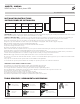
ELECTRICAL SCHEMATIC DIAGRAM / DIAGRAMA DEL ESQUEMA ELÉCTRICO
1. Turn power o from the electrical panel prior to installtion.
1. Apague la corriente del panel eléctrico antes de la instalación.
2. Open the junction box cover on driver and remove the appropriate knockout(s) on the side panel.
2. Abra la tapa de la caja de conexión del controlador y quite el(los) panel(es) eléctrico(es) correspondiente(s) en el panel lateral.
3. Insert the electrical supply cable through the knockout and secure with a cable connector (sold separately).
3. Inserte el cable de suministro eléctrico a través del panel eléctrico y asegúrelo con un conector de cable (se vende por separado).
4. Using quick-connect push-in terminals,connect the green ground wire to the green wire terminal; black wire (hot)to black wire terminal; white wire
(neutral) to white wire terminal.
4. Usando terminales de conexión rápida a presión, conecte el cable de tierra verde al terminal del cable verde; el cable negro (vivo) al terminal del
cable negro; y el cable blanco (neutro) al terminal del cable blanco.
5. Conéctelo a un atenuador de 0-10V (si corresponde) y como se muestra en la cubierta del controlador.
5. Connect to 0-10V dimmer (if applicable)and as shown on driver cover.
6. Vuelva a colocar todo el cableado y las conexiones en la caja y cierre la tapa de forma segura con el tornillo de la tapa.
6. Place all wiring and connections back in to the box and close the cover securely with cover screw.
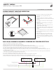
1. Put the pieces of frame to any horizontal surface.
Connect three pieces together with screws
(included).
1. Coloque las piezas de la estructura en cualquier
superficie horizontal. Conecte tres piezas con tornillos
(incluidos).
2. Use a Phillips screwdriver (not included) to tighten
the screws.
2. Utilice un destornillador Phillips (no incluido) para
ajustar los tornillos.
3. Drill four 1/4 in. diameter holes into the four screw
locations marked on the ceiling.
3. Taladre cuatro orificios de 1/4in de diámetro en las
cuatro ubicaciones marcadas en el techo para los
tornillos.
4. Insert a drywall anchor into each of the drilled holes.
4. Inserte un anclaje para paneles de yeso en cada uno
de los orificios.
5. Coloque la cuarta pieza y asegúrela con tornillos.
5. Attach the fourth piece and secure with screws.
6. Turn on the main power. Installation is complete.
6. Encienda la corriente principal. La instalación está
completa.
CONTROLADOR LED
LED DRIVER
Dim-
Atenuar- Atenuar+
Dim+(Violet) / Atenuar+ (violeta)
L (Live/hot) connect black / L (vivo/caliente) cable negro
N (neutral) connect white / N (neutro) cable blanco
G (ground) connect green / G (tierra) cable verde
Dim-(Gray) / Atenuar- (gris)
Dim+ L
L
N
N
Ground
Tierra
CONTROLADOR LED
LED DRIVER
Dim-
Atenuar- Atenuar+
Dim+ L
L
N
N
Ground
Tierra