
User's Manual


Final ass
7
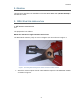
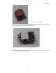
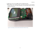
4. The RF-module is attached on top of the interference shield as shown in Figure 8.
When viewed from the side, the contacts of the RF-module must not come in contact
with the interference shield’s slanted sides (Figure 9.). The RF-module must be
pressed for a while to ensure that the adhesive tape has attached itself properly.
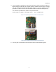
The antenna is positioned as shown in the pictures below.
Antenna type is: 24AWG Full length: 75mm, Gain: 1.9 dBi (max)
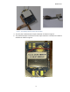
Figure 9 The positioning of the RF-module on the KRO-board
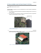
5. The flex print is connected to the connector K16 on the IRC-board, Figure 9.
Figure 8 The positioning of the RF-module on the KRO-board.