
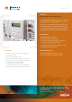
Instruction Manual

Since norms, speci cations and designs are subject to occasional change, please ask for con rmation of the information given in this publication.
Mirion Technologies (MGPI) SA
Route d’Eyguières
FR-13113 Lamanon
France
T +33 (0) 4 90 59 59 59
F +33 (0) 4 90 59 55 18
Mirion Technologies (MGPI) Inc
5000 Highlands Parkway
Suite 150
Smyrna, GA 30082
USA
T +1 770 432 2744
F +1 770 432 9179
Mirion Technologies (MGPI H&B) GmbH
Landsberger Strasse 328a
DE-80687 Munich
Germany
T +49 (0) 89515 13-0
F +49 (0) 89515 13 169
Mirion Commercial (Beijing) Co., Ltd.
Shanghai Jiangchang Commercial Branch
Room 801, 78 Jiangchang SanLu
Zhabei District, Shanghai 200436
PR of China
T +86 21 6180 6920
F +86 21 6180 6924
TK 250
Signal Processing
www.mirion.com
144879EN-C
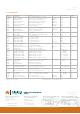
LIST OF MODULES
Type Designation Function Used For Supply Voltage Width
NA 04/06
NA 07.21
NA 31
NA 32
NA 33
NA 34
NA 36
Indicator unit
Pump control unit
Current input unit
Fission chamber unit
RMS input unit
Average value ampli er
SPND input unit
1 or 2 analog indicators 24 × 96 mm
Switches and operating hours counter
c/v-converter 0 ... 10/25/50 μA
Detector voltage and c/f-converter
Main ampli er and RMS-correlator
c/v-converter 0 ... 2.5/5 mA
Differential ampli er
DEK 251
DGK 250
DSK 250
DWK 250
DMK 250
DLK 250
-
24 V
±15 V
±15 V
±15 V
±15 V
±15 V
8/12 T
8 T
4 T
4 T
4 T
4 T
4 T
NB 21
NB 22
NB 28
Binary I/O-board
Decoder board
Binary output board
4 inputs, 8 relays outputs 60 V/0,5 A
4 bit to 1v16, with level shifter
8 relays outputs 125V/1A
DAK, DWK
±15 V
±15 V
±15 V
4 T
4 T
4 T
NE 31
NE 32
Pulse outputs
Pulse shaper
2 insulated 50 Ω pulse buffers
Pulse ampli er, e.g. for iodine monitors DEK 251
±15 V
±15 V
4 T
4 T
NH 32
NH 33
NH 34
NH 36
NH 42
High voltage supply
High voltage supply
High voltage supply
High voltage supply
High voltage supply
0 ... 1 kV, 2 mA max.
0 ... 2 kV, 1 mA max.
0 ... 4 kV, 0,5 mA max.
0 ... 500 V, 4 mA max.
0 ... 800 V, 30 mA max. DWK 250
±15 V
±15 V
±15 V
±15 V
±24 V
8 T
8 T
8 T
8 T
14 T
NI 11
NI 21
NI 22.2
NK 21.2
Standard pulse input
Pulse discriminator
Double window discriminator
Serial interface
2 insulated inputs
2 integral discriminators
2 single channel discriminators
RS 232 or RS 485, insulated
DEK 251
5 V, ±15 V
5 V
5 V, ±15 V
5 V
4 T
0/4 T *
0/4 T *
4 T
NN 01
NN 41
NN 43
NN 51
NN 53
NN 54
DC supply network
24 VDC power supply
24 VDC power supply
230 VAC power supply
230 VAC power supply
230 VAC power supply
Redundant supply & battery inputs
Output voltages: 5 V, ±15V
Output voltages: 5 V, ±15V
Output voltages: 5 V, ±15V
Output voltages: 5 V, ±15V
Output voltages: 24 VDC or 28 VDC
35 VDC max.
18 ... 32 VDC
18 ... 32 VDC
195 ... 255 VAC
195 ... 255 VAC
195 ... 255 VAC
4 T
4 T
8 T
4 T
8 T
8 T
NP 31
NR 17
NR 31
NS 01
Test generator
Relay board
Relay board
Key switch board
Test signal 0 ... 10 V/20 mA adjustable
6 relays, 2 change overs each
16 relays, 2 contacts each
2 key switches, test plugs
DMK 250 ±15 V
15 or 24V
15 V
5 V
4 T
4 T
4 T
4 T
NT 31
NT 61
Isolated buffer ampli er
Isolated buffer ampli er
1 ... 4 × 0 ... 10V/0 ... 20mA
Various input/output combinations
±15 V
24 ... 230 VAC/DC
4 T
4 T
NZ 12
NZ 21
Main processor board
I/O processor board
With display and keys
2 counters, 4 analog I/Os each
5 V
5 V, ±15 V
20 T
0/4 T *
NV 101
NV 102
NV 320
TKV 23
c/f converter
c/f converter
Pulse pre-ampli er
Wide range pre-ampli er
0.1 pA … 0.3 μA, 800 V detector supply
0.1 pA … 1mA, various detector voltages
For neutron detectors
For wide range ssion chambers
DAK 250
DWK 250
15 ... 32 VDC
15 ... 32 VDC
±15 V
±15 V
Box
Box
Box
Box
notice: T = 2/10” = 5.08 mm
* without front panel, arranged behind NZ 12