
Specifications

FleX-Net
TM
Installation and Operation Manual
55
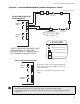
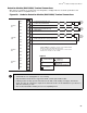
Detection Module (DM-1008A) Terminal Connections
Wire devices to terminals as shown below. See wiring tables, and Appendix A for electrical specifications and
document LT-1023 for compatible devices.
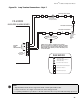
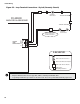
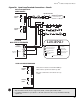
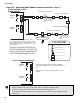
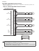
Figure 40: Hardwire Detection Module (DM-1008A) Terminal Connections
Note:
• Terminal blocks are “depluggable” for ease of wiring.
• All power limited circuits must use type FPL, FPLR, or FPLP power limited cable.
• Initiating circuits are fully supervised and rated for 22 VDC, 3 mA standby, 5 mV ripple, 50 mA max
alarm. They may be configured as required. The alarm threshold is 21 mA. Maximum loop resistance is
100 ohms, 50 ohms per side.
• All conventional hardwire initiating circuits are Compatibility ID "A".
SUPERVISORY OR
WATERFLO W
SWI TCH (NO)
HEAT DETECTOR
Leg en d:
SMOKE DETECTOR
3.9K 1/2W ELR LISTED S5434
MODEL MP-300
MANUFACTURED BY MIRCOM
INI 1+
INI 1-
INI 2+
INI 2-
INI 3+
INI 3-
INI 4+
INI 4-
STYLE B/ D
INI 2
STYLE B/ D
INI 1
PULL STATION
STYLE B
(CLASS B)
WIRING
STYLE B
(CLASS B)
WIRING
STYLE D
(CLASS A)
WIRING
SUPERVISED INITIATING CIRCUIT #2
(SUPERVISORY OR WATERFLOW ZONE)
(POWER LIMITED)
SUPERVISED INITIATING CIRCUIT #1
(ALARM ZONE) (POWER LIMITED)
SUPERVISED INITIATING CIRCUIT #3
(ALARM ZONE) SEE STYLE D NOTE (POWER LIMITED)
INI 5+
INI 5-
INI 6+
INI 6-
INI 7+
INI 7-
INI 8+
INI 8-
STYLE B/ D
INI 4
STYLE B/ D
INI 3
Style D Note: Initiating circuits of the DM-1008A
must be either all Style B (Class B)
or all Style D (Class A). If Style D is selected, the
number of circuits is cut in half.