
Specifications

FleX-Net
TM
Installation and Operation Manual
43
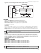
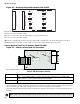
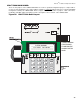
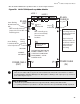
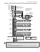
Wire the ALCN-792M Quad Loop Adder module as shown in Figure 28 below.
Figure 28: ALCN-792M Quad Loop Adder Module
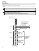
Wiring The Addressable Loops
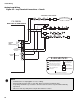
There are two addressable loops present on this board that are wired in the same manner as shown in
the wiring diagrams beginning with Figure 34. Although these drawings show only Loop 1;Loop 2 is wired
in the same way as Loop 1 is.
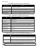
Notes for ALCN-792M:
• All circuits are power limited and must use type FPL, FPLR, or FPLP power limited cable.
• Loop wiring: maximum loop resistance is 40 ohms total. These lines power-limited and fully supervised.
+ - + -
S
S
+ - + -
ALARM OUT
LOOP 1
LOOP 2
RS-485
P4
P2
P6
P1
P3
RS-485
ADDRESS
DIP SWITCH
RS-232
Debug
Interface
Loop 1
Active LED
Loop 2
Active LED
Four shaded
mounting holes are
for Daughter board
ALCN-792D
Top 2 holes and
bottom 2 holes are
used for the ALCN-
792 Quad Loop
Adder module
mounting
JTAG PORT
DIP SWITCHES ARE FOR THIS
BOARD’S ADDRESS. SW1-1
IS THE LEAST SIGNIFICANT
DIGIT (BINARY). ACTIVE
POSITION IS ON.
P5
SW1
POWER CABLE
(OUT)
POWER CABLE
(IN)
JW2- normally shorted, a
jumper is here to enable
watchdog timer.
JW1- normally open,
pins are momentarily
shorted to reset
hardware.
B
A
A
B
8
1
Green ashing
RS-485 heartbeat
LED
Green ashing
heartbeat LED for
on board processor
OUT
CABLE IN
Daughter Board
Connector
COM (-)