SRM-312 Series Remote Relay FA-300 SERIES REMOTE RELAY Installation and Operation Manual LT-1001 Rev.
1.0 Introduction 5 2.0 Mechanical Installation 5 3.0 Functional Setup 6 3.1 Jumpers ......................................................................................................................... 6 3.2 DIP Switches .................................................................................................................. 7 3.2.1 Dip Switch DSW1-1 to 1-3 ............................................................................................. 7 3.2.2 Dip Switch DSW1-4 ...
7.4.1 International Warranty .................................................................................................... 13 7.4.2 Conditions to Void Warranty .......................................................................................... 14 7.5 Warranty Procedure ....................................................................................................... 14 7.6 Disclaimer of Warranties ..................................................................................
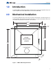
Introduction 1.0 Introduction The Model SRM-312 Smart Relay Module provides twelve supervised configurable relays and comes complete with a white SRM-312W or red enclosure SRM-312R. 2.0 Mechanical Installation To mount the SRM-312 open the front door, and mount the backbox to the wall using the four screws provided. This enclosure may also be mounted to a 4” square electrical box. There are two conduit areas provided at the bottom of the enclosure. 8.2" 6.3" 0.75” FOUR MOUNTING HOLES 7.5" 9.
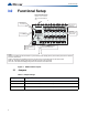
Functional Setup 3.0 Functional Setup Place 120 EOL Jumper JW51ohm is used on resistor last betweenONLY. + andRemove - on theallRSSRM-312 485 on last wired JW51 jumpers exceptSRM-312 for the last address. only. DIP Switch for relay address S A Z9 S 9&10 8&9 RLY. 10 Z10 A S RLY. 11 A Z11 S 11&12 10&11 RLY. 12 Z12 A S NO N C A 12 4 5 6 7 8 24VDC +IN/OUT- Leave jumpers JW48, JW49 and JW50 intact on board. Z1 S 1&2 A RLY. 1 Z2 S 2&3 A RLY. 2 Z3 S 3&4 A Z4 S 4&5 A RLY.
Functional Setup 3.2 DIP Switches ! Attention: Dip Switch DSW 1-6 and DSW 1-8 are always to be set to OFF. There is one bank of DIP switches to be set. DSW1 is found at the top left hand corner and is used to select the smart relay address. Valid addresses are 1 to 6 inclusive, for FA-300 Series and FR-320 Series Fire Alarm Panels; 1 to 7 inclusive for FX-350/351 and FX-3500/FX3500RCU Series. Set address as described in 3.2.1 Dip Switch DSW1-1 to 1-3. 3.2.
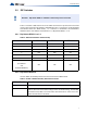
Configuration of the Relays 3.2.3 Dip Switch DSW1-5 (FR-320 only) Used to enable added support for hazard zone message for the FR-320. This option is enabled by putting DSW1-5 to the “ON” position.When this option is enabled, relay 1 to 6 will show the status for Hazard Area 1 and Hazard Area 2 as shown in the table below. Table 4 Enabled FR-320 Hazard Area Status Description Hazard Area 1 Hazard Area 2 RLY1 RLY2 RLY3 RLY4 RLY5 RLY6 Alert Alarm Release Alert Alarm Release 3.2.
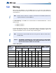
Wiring 5.0 Wiring Wire from the last SRM-312 to the next SRM-312 and so on; then from the first SRM-312 to the Fire Alarm Panel. There are only two connections to be made, one for power and one for the RS-485 loop. i Note: Ensure that the 120 E.O.L. resistor is connected to the RS-485 positive and negative terminals on the last SRM-312. The RS-485 Wiring to the SRM-312 is recommended to be Twisted Shielded Pair. The wire gauge may be: • 22 AWG up to2000 ft. • 20 AWG up to4000 ft.
Specifications & Features 6.0 Specifications & Features 6.1 Enclosure: • 6.2 6.3 Enclosure may be mounted on a 4” square Electrical Box or on a wall. Electrical Specifications • 24 VDC nominal voltage. • Common LEDs DISCNN (Aux. Disconnect), TX/RX (Transmit/Receive), PWR ON, CPU FAIL and individual relay status LED indicators. • 28V DC, 1A maximum per contact (resistive load) • 12 programmable relays available. • Not Expandable. • Standby 30 mA Max., Alarm 140 mA Max.
Warranty and Warning Information 7.0 Warranty and Warning Information 7.1 i 7.2 Warning Please Read Carefully Note: This equipment is subject to terms and conditions of sale as follows: Note to Installers This warning contains vital information. As the only individual in contact with system users, it is your responsibility to bring each item in this warning to the attention of the users of this system.
Warranty and Warning Information may fail to operate as expected. Regular testing and maintenance will keep the system in good operating condition. 7.3.4 Compromise of Radio Frequency (Wireless) Devices Signals may not reach the receiver under all circumstances which could include metal objects placed on or near the radio path or deliberate jamming or other inadvertent radio signal interference. 7.3.
Warranty and Warning Information 7.3.9 Telephone Lines If telephone lines are used to transmit alarms, they may be out of service or busy for certain periods of time. Also the telephone lines may be compromised by such things as criminal tampering, local construction, storms or earthquakes. 7.3.
Warranty and Warning Information 7.4.2 Conditions to Void Warranty This warranty applies only to defects in parts and workmanship relating to normal use. It does not cover: 7.
Warranty and Warning Information obtain an authorization number. Mircom will not accept any shipment whatsoever for which prior authorization has not been obtained. Products which Mircom determines to be repairable will be repaired and returned. A set fee which Mircom has predetermined and which may be revised from time to time, will be charged for each unit repaired. Products which Mircom determines not to be repairable will be replaced by the nearest equivalent product available at that time.
CANADA - Main Office 25 Interchange Way Vaughan, ON L4K 5W3 Tel: (888) 660-4655 (905) 660-4655 Fax: (905) 660-4113 U.S.A 4575 Witmer Industrial Estates Niagara Falls, NY 14305 Tel: (888) 660-4655 Fax: (888) 660-4113 TECHNICAL SUPPORT North America Tel: (888) Mircom5 (888) 647-2665 International Tel: (905) 660-4655 © Mircom 2014 Printed in Canada Subject to change without prior notice www.mircom.