
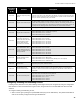
Specifications

Walk Test Operation
48
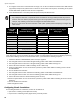
Display Configuration
The main and adder display modules on the front panel are automatically updated to display all circuits found
whenever the function “Resize - Adder Module Number and Type Configuration” is performed. The main display
module has dedicated trouble LEDs for the four indicating circuits on the main fire alarm module. The eight initiating
circuits (four in Class A mode) also on the main fire alarm module are annunciated on the first column of display
points (from top to bottom). Any adder module circuits are displayed after the base system input circuits in the same
order as the adder modules have been installed (that is from right to left). For example, if there are two eight-circuit
initiating circuit adder modules and one four-circuit indicating circuit adder module, the main display will annunciate
24 initiating circuits followed by four indicating circuits. If the fire alarm control panel is configured for Class A (Style
D) initiating circuits, then the number of initiating circuits is cut in half, so that in the example above, there will only be
a total of 12 initiating circuits annunciated, followed by the four adder indicating circuits. Refer to Figure 25 on
page 32 to see how the first 24 circuits are mapped to display points.
Any configured RA-1000 Series Remote Annunciators automatically match the main fire alarm control panel
displays, except that there will be no annunciation of Common Alarm, Common Supervisory, Battery/Charger
Trouble, Ground Fault and Four-Signal trouble indicators.
Walk Test Operation
A walk test allows you to verify the initiating circuit wiring in a system. The walk test is a special configuration mode
function (function 80 on the configuration DIP switches). Circuits to be tested are identified using the circuit
disconnect switches. Activation of any initiating circuit that has been selected for the walk test will cause the audible
indicating circuits (not strobes) to activate briefly for a number of short bursts corresponding to the selected circuit
number. If the first selected circuit is activated, the indication circuits will sound for one burst. If the second selected
circuit is activated, the indication circuits will sound for two bursts, and so on. This means that if, for example, circuits
1, 6, 23, and 32 were selected for the walk test, they would sound with 1, 2, 3, and 4 bursts respectively. The
maximum number of circuits that may be set at any one time for a walk test is 15. The burst interval is half a second
on half a second off. After the sounding pattern has been sent on the indicating circuits, the initiating circuit is reset
and tested again. If it is still active (in alarm) the pattern will be re-sent. Trouble on any initiating circuit selected for
the walk test causes the indicating circuits to be activated continuously for 5 seconds.
Alarm verification and water-flow alarm retard operations are disabled on circuits being walk tested. All circuits not
selected for the walk test continue to function normally. If a circuit was disconnected before walk test mode was
entered and is not selected for the walk test, it remains disconnected while the walk test is active. The walk test
operation is disabled if the fire alarm control panel is in alarm or goes into alarm while walk test mode is active.
Notes:
• The feature called “Output Circuit Correlations Enabled” must be ON for indicating circuit correlations to
operate (see Configuration Features on page 44), otherwise all indicating circuits will be common alarm.
This means that they will all activate with any input circuits configured as alarms. Relay circuits are
always enabled for correlations.
• If the system is configured as two stage, any second stage / general alarm (caused by the Auto General
Alarm timer, the General Alarm button on the front panel or remote annunciator, or by a General Alarm
initiating circuit) condition activates all indicating circuits whether or not they are correlated.
Notes:
• If a UDACT is used with the system, all walk test events will be reported to the monitoring agency.
Instruct the monitoring agency to ignore reported events during the walk test.
• If there is no activity for one hour, the system will return to normal operation, but will remain in a trouble
condition until the DIP switches are reset and the panel is reset.