
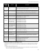
Specifications
FA-1000
Installation and Operation Manual
47
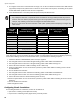
With the factory default configuration, all outputs are configured to activate with any inputs configured as alarms. If
output circuit correlations are enabled (see Configuration Features on page 44), outputs must be configured to one
or more inputs to activate at all. This configuration is referred to as a correlation. There are two configuration
options: correlated individual outputs to one or more inputs, or correlated individual inputs to one or more outputs.
Output circuits may be correlated to as many input circuits as desired, and vice-versa.
Correlation by Input Circuit
1. Raise the Config DIP switches 2 and 8. Pause for about three seconds.
2. Turn on (up position) only one input circuit's (initiating circuit / detection zone) disconnect switch. If you turn on
more than one input circuit disconnect switch at one time, the selected input circuit's yellow trouble LED and
the yellow trouble LEDs of any output circuits (indicating circuit / signal zone, or relay circuit) that are already
correlated to that input will illuminate, and the function will not operate.
If you require only a correlations check, repeat step 2 to step through from one input circuit to another, one at a
time.
If you would like to set new correlations for the selected input circuit,
3. Turn on (up position) the disconnect switch for desired output circuits.
4. Press the yellow button for one second. After a pause the yellow trouble LEDs for the newly correlated output
circuits will illuminate.
5. Lower all DIP switches to the OFF position and press the System Reset button.
Correlation by Output Circuit
1. Raise the Config DIP switches 2 and 7. Pause for about three seconds.
2. Turn on (up position) only one output circuit's (indicating circuit / signal zone or relay circuit) disconnect switch.
If you turn on more than one input circuit disconnect switch at one time, the selected input circuit's yellow
trouble LED and the yellow trouble LEDs of any output circuits (indicating circuit / signal zone, or relay circuit)
that are already correlated to that input will illuminate, and the function will not operate.
If you require only a correlations check, then repeat step 2 to step through from one output circuit to another, one at
a time.
If you would like to set new correlations for the selected output circuit,
3. Turn on (up position) the disconnect switch for desired output circuits.
4. Press the yellow button for one second. After a pause the yellow trouble LEDs for the newly correlated input
circuits will illuminate.
5. Lower all DIP switches to the OFF position and press the System Reset button.
At present, only the following types of circuit correlations are possible:
• Alarm circuits (Verified or Non-Verified, Sprinkler or Water-Flow) to indicating circuits or relays.
• General Alarm circuits to indicating (they are automatically correlated to all indicating circuits).
• Supervisory circuits (Latching or not) to relays.
• Monitor circuits to relays.
• Trouble-Only circuits to relays.
• See notes on next page.