
Specifications
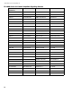

System Configuration
46
2. To configure circuits to be of that selected circuit type, turn on all of the desired circuit disconnect DIP switches
(up position) and press the yellow button for about one second. After a short pause, the initiating circuit yellow
trouble LEDs will be updated to show the new configuration.
3. Lower all DIP switches to the OFF position and press the System Reset button.
For example, if you wanted Class B operation in a system with eight initiating circuits and four indicating circuits
(main board only), the first six initiating circuits as normal non-verified alarms, the last two as latching supervisory,
and the last indicating circuit as a non-silenceable strobe, you would use the following sequence:
1. Follow the Restore to Default/Resize (Class A or B) on page 43.
2. Set Config DIP switch to 0010 0000. All eight initiating yellow trouble LEDs should illuminate.
3. Set Config DIP switch to 0010 0101. All eight initiating yellow trouble LEDs should go out.
4. Set the disconnect switches to ON for initiating circuits 7 and 8 only.
5. Press the yellow button for one second. After a pause the yellow trouble LEDs for initiating circuits 7 and 8
should illuminate.
6. Turn off all disconnect switches.
7. Set Config DIP switch to 0011 0000. All four indicating yellow trouble LEDs should illuminate.
8. Set Config DIP switch to 0011 0011. All four indicating yellow trouble LEDs should go out.
9. Set the disconnect switch to ON for indicating circuit four only.
10.Press the yellow button for one second. After a pause the yellow trouble LED for initiating circuit four should
illuminate.
11. Turn off all disconnect switches.
12.Exit configuration mode.
Configuring Circuit Correlations
As a working definition for correlations, circuits can be defined as:
• input circuits = initiating circuits (detection zones)
• output circuits = indicating circuits (signal zones), and relay circuits
Notes:
• Any subsequent selection of a particular circuit as a different circuit type will supercede the previous
selection. Also note that the physical circuit type must be appropriate for the selected circuit type. For
example, only indicating circuits can be configured as silenceable strobes.
• Be sure to reset circuit disconnect switches to OFF (down position) before attempting to configure any
other circuits.
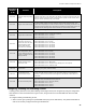
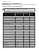
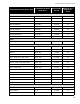
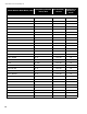
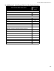
Config DIP
Switch
Position (1-8)
Initiating Circuit
(Detection Zone) Type
Config DIP
Switch
Position (1-8)
Indicating Circuit (Signal
Zone) Type
0010 0000 Normal (Non-Verified Alarm) 0011 0000 Silenceable Audible Signal
0010 0001 Verified Alarm 0011 0001 Non-Silenceable Audible Signal
0010 0010 Sprinkler Alarm 0011 0010 Silenceable Strobe
0010 0100 Non-Latching Supervisory
0010 0110 General Alarm
0010 1000 Trouble Only
0010 0101 Latching Supervisory
0010 0111 Monitor