
Specifications

FA-1000
Installation and Operation Manual
45
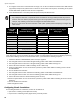
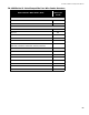
Configuring Initiating and Indicating Circuits
Initiating circuits (detection zones) and indicating circuits (signal zones) are configured by using the configuration
DIP switches to select the desired circuit type function, along with the circuit trouble LEDs and disconnect DIP
switches.
To configure initiating and indicating circuits,
1. Select a circuit type by raising the specified DIP switch(es) (see the table below). The yellow trouble LED for
each circuit currently configured as that type will illuminate.
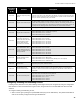
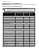
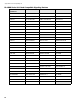
0001 0001
Common Supervisory Relay
Action
An illuminated yellow LED indicates that the common supervisory relay will follow the
common alarm status. If the yellow LED is off (default), the common supervisory relay will
follow the common supervisory status. Use this feature to provide an extra common alarm
relay if a common supervisory relay is not needed.
0001 0010 Signal Circuit Isolator Option
An illuminated yellow LED indicates that if a short circuit exists on any indicating circuit and
an alarm condition follows, then those indicating circuits will be activated anyway. If the
yellow LED is off (default), then under the same conditions, the indicating circuits will not be
activated to prevent wasting power. This feature is needed when signal isolator devices are
employed so that indicating circuits will be activated even under shorted conditions.
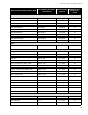
0011 1000 Show Relay Circuits All display points assigned to relay circuits will be lit.
0000 1010 Signal Silence Inhibit Timer
Yellow LED does not flash = Disabled (default)
Yellow LED flashes 1 time = 1 minute (ULC required)
Yellow LED flashes 2 times = 2 minutes
Yellow LED flashes 3 times = 3 minutes
0000 1011
Auto Signal Silence timer
(This timer cannot be set
shorter than either the Auto
General Alarm or Signal
Silence Inhibit timers, if
those timers are enabled)
Yellow LED does not flash = Disabled (default)
Yellow LED flashes 1 time = 5 minute
Yellow LED flashes 2 times = 10 minutes
Yellow LED flashes 3 times = 15 minutes
Yellow LED flashes 4 times = 20 minutes
Yellow LED flashes 5 times = 30 minutes
0000 1100
Auto General Alarm Timer
(Leave disabled unless the
system is configured for Two
Stage operation)
Yellow LED does not flash = Disabled (default)
Yellow LED flashes 1 time = 5 minute
Yellow LED flashes 2 times = 10 minutes
Yellow LED flashes 3 times = 15 minutes
Yellow LED flashes 4 times = 20 minutes
Yellow LED flashes 5 times = 30 minutes
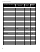
0000 1101
Audible Indicating Circuit
Evacuation Code
Yellow LED flashes 1 time = Continuous
Yellow LED flashes 2 times = March Time
Yellow LED flashes 3 times = Temporal Code (default) (UL & ULC required)
Yellow LED flashes 4 times = California Code
0000 1110
Number of Remote
Annunciators
The yellow LED flashes 0 to 8 times to indicate the number of remote annunciators
expected by the system. (default 0 flashes)
0000 1111
PR-300/DACT alarm
Transmit Silence Option
An illuminated yellow LED indicates that the alarm transmit signal from the PR-300 or DACT
will be silenceable with the activation of the signal silence button. If the yellow LED off
(default), it indicates that the alarm transmit signal from the PR-300 or DACT will not be
silenceable.
0001 0000 AC Power Fail Delay Time
The AC Power Fail trouble signal from the PR-300 or the DACT can be delayed when the
only trouble on the fire alarm panel is AC power fail.
Yellow LED flashes 0 times = No Delay (default)
Yellow LED flashes 1 time = 1 Hour
Yellow LED flashes 2 times = 2 Hours
Yellow LED flashes 3 times = 3 Hours
DIP Switch
Position
(1-8)
Features Description