
Specifications
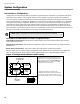

System Configuration
44
5. Set the Config DIP switch to 0100 0000 (resize system
1
). Wait five seconds.
6. Press the yellow and red buttons together for five seconds. Wait 10 seconds.
The system is now ready for further configuration, or configuration mode may be exited if the default settings are
acceptable.
Resize System (Set Circuit Adder Module Number and Type)
You may resize the system without performing a full “restore to defaults” if the only change you made to the system
was adding or removing an adder display module or a circuit module. Otherwise, perform the “resize system”
procedure as a part of a full “restore to defaults”, failure to do so may cause errors while assigning the circuit-specific
configuration.
To resize a system after circuit adder modules were added after existing modules,
1. Set Config DIP switch to 0100 0000 (resize system
1
). Wait five seconds.
2. Press the yellow and red buttons together for five seconds. Wait ten seconds.
The system is now ready for further configuration, or configuration mode may be exited if the default settings for the
added modules are acceptable.
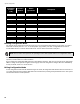
Configuration Features
There are two types of features: those that can be turned on and off, and those with multiple settings. For on and off
features, press the yellow button to toggle the settings on or off. The yellow LED is illuminated for ON, and not
illuminated for OFF. For multiple setting features, the yellow LED flashes a number of times to indicate the setting,
then pauses. Use the yellow button to change the selected setting. Be sure to pause for about three seconds after
changing the configuration DIP switches or pressing the yellow button to see the results.
Note: The yellow LED indicates how many adder modules (plus the main board) are found, not how many
the system is configured to accept. If the number of adder modules found is different from the number
the system is configured for, the system will go into a trouble condition.
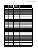
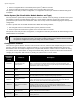
DIP Switch
Position
(1-8)
Features Description
0000 0001
Style D/B (Class A/B)
Initiating Circuits
An illuminated yellow LED indicates that all initiating circuits (detection zones) are Class A
(Style D). An LED that is off (default) indicates that they are all Class B (Style B). This
feature can be checked at any time, but must only be changed as described in Restore to
Default/Resize (Class A or B) on page 43.
0000 0010
Manual Signal Silence
Enable
An illuminated yellow LED (default) indicates that manual silence is enabled.
0000 0011 Fire Drill Enable An illuminated yellow LED (default) indicates that fire drill is enabled.
0000 0100
Two Stage Operation
Enabled
An illuminated yellow LED indicates that the system is set for two stage operation. If the
LED is off (default), the panel is configured for single stage operation.
0000 0101
Common Alarm Relay
Operation
An illuminated yellow LED indicates that if the system is set for two stage operation, the
common alarm relay will only operate during the general alarm stage. If the LED is off
(default), the common alarm relay will operate during both stages.
0000 0110
Output Circuit Correlations
Enabled
An illuminated yellow LED indicates that the output circuits (indicating circuits and
indicating) operate according to any set correlations (see Configuring Circuit
Correlations on page 46). If the yellow LED is off (default), all output circuits are common
alarm; all outputs turn on for any alarm input.
0000 0111
Waterflow and Sprinkler
Retard Operation
An illuminated yellow LED indicates that waterflow retard is enabled. If the LED is off
(default), it indicates that retard is disabled.
0000 1001
Aux Disc and Programmable
Relays
An illuminated yellow LED (default) indicates that correlated relays are disconnected by
auxiliary disconnect.