
Specifications

FA-1000
Installation and Operation Manual
43
Factory Default Configuration
The system as shipped from the factory is configured with no adder modules, and with set defaults as outlined
below:
• All initiating circuits are Style B (Class B) non-verified alarms (any alarm on any initiating circuit activates all
indicating circuits)
• Indicating circuits are all common alarm and set as silenceable, temporal code. If shorts exist on any indicating
circuits, then they will not activate on alarms.
• Manual signal silence is enabled
• Fire drill is enabled
• Two stage is disabled (the system will operate single stage)
• If a two stage system is enabled, the common alarm relay operates on both stages
• All indicating and relay correlations are set to common alarm activation
• Water-flow retard operation is disabled
• Aux disconnect will disconnect correlated relays
• The Signal Silence Inhibit timer, Auto Signal Silence timer, and the Auto General Alarm timer are disabled
• The systems assumes there are no remote annunciators
• Relay adder module(s) activate only on common alarm
• The system assumes that there are no adder modules
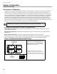
Restore to Default/Resize (Class A or B)
Restore the system to the default configuration whenever you would like to restore the factory default configuration,
and whenever circuit adder modules (detection, signal, or relay) are added, removed, or re-arranged. Restoring the
system to the default configuration is performed slightly differently depending on whether the system is intended to
operate with Class B (Style B) or Class A (Style D) initiating circuits (detection zones).
Class B (Style B) Restore Defaults
1. Set the Config DIP switch to 0111 1111 (restore defaults). Wait five seconds.
2. Press the yellow and red buttons together for five seconds. Wait five seconds.
3. Set the Config DIP switch to 0000 0001 (select Class/Style). Wait five seconds.
4. Press the yellow button until yellow LED turns off.
5. Set the Config DIP switch to 0100 0000 (resize system
1
). Wait five seconds.
6. Press the yellow and red buttons together for five seconds. Wait ten seconds.
Class A (Style D) Restore Defaults
1. Set the Config DIP switch to 0111 1111 (restore defaults). Wait five seconds.
2. Press the yellow and red buttons together for five seconds. Wait five seconds.
3. Set the Config DIP switch to 0000 0001 (select Style/Class). Wait five seconds.
4. Press the yellow button until yellow LED turns on.
Note: Remember to set the main fire alarm board and detection adder module jumpers for the
appropriate Class (Style) (see Module Settings on page 13), and that the Class (Style) setting is global -
for all initiating circuits.
1. During the resize (set circuit adder module number and type) part of the operation, the yellow LED flashes to indicate how many adder
display modules (in addition to the main display module) and circuit adder modules (including the main board) are found. The yellow
LED indicates the number of adder display modules followed by the number of circuit adder modules. If no adder modules are found,
the LED flashes once; if one adder module is found it flashes twice, and so on. For example, if the system has one adder display
module and two circuit adder modules, the yellow LED will flash two times (once for the main display module and once for the adder
display module), pause, flash three times (once for the main board and once for each of the adder modules), then pause again. This
sequence is then repeated.