
Specifications

FA-1000
Installation and Operation Manual
41
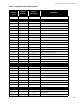
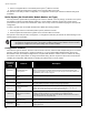
Table 6 Configuration DIP Switch Functions
DIP Switch
Position
(1-8)
Function
Number
Button
Operations
Description
0000 0000 00 None Normal Operation (not in configuration mode)
Features
0000 0001 01 Yellow Select Style D/B (Class A/B) Initiating Circuits
0000 0010 02 Yellow Manual Signal Silence Enable
0000 0011 03 Yellow Fire Drill Enable
0000 0100 04 Yellow Two Stage Operation
0000 0101 05 Yellow Common Alarm Relay Operation
0000 0110 06 Yellow Output Circuit Correlations Enabled
0000 0111 07 Yellow Water Flow Alarm and Sprinkler Alarm Retard Operation
0000 1000 08 Yellow Reserved for Future Use
0000 1001 09 Yellow Aux Disconnect disconnects Correlated Relays
0000 1010 0A Yellow Signal Silence Inhibit timer
0000 1011 0B Yellow Auto Signal Silence timer
0000 1100 0C Yellow Auto General Alarm timer
000011 01 0D Yellow Evacuation Code Selection
0000 1110 0E Yellow Number of Remote Annunciators
0000 1111 0F Yellow Alarm Transmit Silence Option
0001 0000 10 Yellow AC Power Fail Delay Time
0001 0001 11 Yellow Common Supervisory Relay Action
0001 0010 12 Yellow Signal Circuit Isolator Option
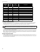
Initiating Circuits/ Detection Zones
0010 000 20 Yellow Normal (Non-Verified) Alarm
0010 0001 21 Yellow Verified Alarm
0010 0010 22 Yellow Sprinkler Alarm
0010 0011 23 Yellow Water Flow Alarm
0010 0100 24 Yellow Non-Latching Supervisory
0010 0101 25 Yellow Latching Supervisory
0010 0110 26 Yellow General Alarm
0010 0111 27 Yellow Monitor
0010 1000 28 Yellow Trouble Only
Indicating Circuits/Signal Zones
0011 0000 30 Yellow Silenceable
0011 0001 31 Yellow Non-Silenceable
0011 0010 32 Yellow Silenceable Strobes