
Specifications
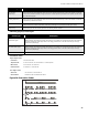

System Configuration
40
System Configuration
Introduction to Configuration
Configuration of the FA-1000 Fire Alarm Control Panel is performed by a combination of configuration DIP switch
settings and button presses. Circuit-related operations are correlated to their respective disconnect switches.
You can access the configuration DIP switches from the main display module after removing the protective lexan
cover. The DIP switches are labelled as CONFIG. 1 to 8. The circuit (zone) disconnect switches are re-defined as
circuit (zone) select during configuration. Make sure you have set the circuit disconnect switches to the desired
settings before exiting configuration mode. Normal system operation is suspended while configuration mode is
active. You enter configuration mode whenever any of the configuration DIP switches are set as per the functions
listed in the Table 3 on the following page, and you exit configuration mode by turning all the DIP switches OFF (put
switches in the bottom or OFF positions), then pressing the System Reset button.
Three buttons and LED indicators are used in configuration mode:
Acknowledge (yellow button): This becomes a "Select Setting" button and the LED indicator may show the
current status of a function.
General Alarm (red button): This becomes a "Confirmation" button for some functions, used together with the
Yellow Button.
Buzzer Silence (blue button): This button performs its normal function of silencing the buzzer.
All other buttons are non-functional during configuration mode. Additionally, the Green Power “ON” LED will be
“OFF” during configuration mode. Common trouble LED will flash to test. Config LED (amber) will be on.
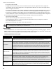
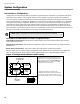
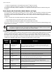
Figure 27 Configuration Indicators and Controls
Note: While in configuration mode the fire alarm control panel is not operating.
The figure to the left shows the positions of the
configuration DIP switch and the yellow and red
buttons. Each has a matching LED indicator of the
same color. Note that the labels Acknowledge and
General Alarm will only be shown in an FA-1000
configured as a two-stage system.
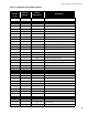
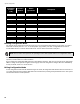
Configuration functions are selected by the
configuration DIP switches as follows in Table 3 on
the next page. Note that a switch position of "0" is
"OFF" (bottom position) and "1" is "ON" (top position).
1 8
RED BUTTON
& RED LED
GENERAL
ALARM
BUZZER
SILENCE
SIGNAL
SILENCE
CONFIG.
ACKNOW-
LEDGE
YELLOW BUTTON
& YELLOW LED