
Specifications
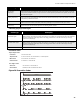
FA-1000
Installation and Operation Manual
35
the panel, but it is still in the first stage) cancels the timer and turns the Acknowledge LED on steady amber.
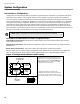
General Alarm Button (Red)
If the panel is not configured for two stage operation, this button does nothing. If the panel is configured for two
stage operation, pressing the General Alarm button immediately sends the panel into second stage General Alarm.
It will also re-activate the signals if they have been silenced during General Alarm. The General Alarm condition
remains active until the panel is reset.
Auxiliary Disconnect Button (Orange)
Pressing the Auxiliary Disconnect button activates the Auxiliary Disconnect function. Pressing the button again
deactivates the function.
Lamp Test Button (Orange)
Pressing the Lamp Test button causes all front panel indicators to illuminate and sounds the buzzer steadily. If
Lamp Test is active for more than ten seconds, the Common Trouble LED is activates.
Buzzer Silence Button (Blue)
Activation of the Buzzer Silence button while the buzzer is sounding silences the buzzer. The buzzer will resound if
there is a subsequent event. Pressing the button when the buzzer is not sounding has no effect.
Circuit Status Indicators
There is one pair of circuit Status LEDs for each initiating, indicating, and relay circuit. The first four indicating
circuits on the main fire alarm module are part of the common indicators. All other circuits (including the first eight
initiating circuits on the main fire alarm module) are arranged in columns of eight indicators numbered from one to
eight. For each circuit, the upper circuit Status LED may be red or amber, and will either be steadily illuminated or
flashing at either the fast flash or trouble flash rates, depending on the operation. The amber Circuit Trouble LED
flashes at the trouble flash rate when active. The Status LED is used on initiating circuits only.
After the first eight initiating circuits (corresponding to the first column of circuit LED's) the circuit LEDs are
configured in the same order as any adder modules. If there are insufficient display adders for the number of circuits
on the panel, the last circuits will not be displayed. If there are too many displays for the number of circuits on the
panel, the unassigned ones will be unused.
Alarm Circuit Indicators
The operation of alarm circuit indicators applies to initiating circuits configured as verified alarm, non-verified alarm,
water-flow alarm, sprinkler alarm, or general alarm circuits.
• The Circuit Trouble LED flashes at the trouble flash rate to indicate circuit trouble (open circuit or Style D /
Class A trouble) or a disconnected circuit. It always turns off when the circuit is in alarm.
• The Circuit Status LED illuminates steady red when the circuit is in alarm. On verified alarm circuits, sprinkler
alarm, and water-flow alarm circuits, the circuit Status LED will illuminate at the fast flash rate during the pre-
alarm condition. This LED will also flash at the fast flash rate while an active circuit is being un-disconnected.
Supervisory Circuit Indicators
The operation of supervisory circuit indicators applies to initiating circuits configured as latching or non-latching
supervisory circuits.
• The Circuit Trouble LED flashes at the trouble flash rate to indicate circuit trouble (open circuit or Class A (Style
D) trouble) or a disconnected circuit. It always turns off when the circuit is in alarm.
• The Circuit Status LED turns on steady amber when the corresponding circuit is in alarm. This LED will also
flash at the fast flash rate while an active circuit is being reconnected.
Monitor Circuit Indicators
The operation of monitor circuit indicators applies to initiating circuits configured as monitor circuits.
• The Circuit Trouble LED flashes at the trouble flash rate to indicate circuit trouble (open circuit or Class A (Style
D) trouble) or a disconnected circuit. It always turns off when the circuit is in alarm.