
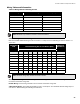
Specifications
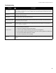
Indicators, Controls, and Operation
34
configuration mode. If the panel is left in either mode for over an hour with no operator activity, this LED will flash at
the trouble flash rate.
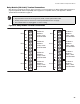
Auxiliary Disconnect LED
The amber Auxiliary Disconnect LED flashes at the trouble flash rate after the Auxiliary Disconnect button is
pressed. It turns off after the button is pressed a second time. When on, it indicates that common alarm and
common supervisory relays are not activated, and programmable relays (if disconnect is enabled) are not activated.
The city tie module, if installed, is also inactive.
Signal Silence LED
The amber Signal Silence LED flashes at the trouble flash rate when indication circuits are silenced either by the
Signal Silence button or by the Auto Signal Silence timer. It turns off when the signals are re-sounded by a
subsequent alarm.
Battery/Charger Trouble LED
The Battery/Charger Trouble LED flashes amber at the trouble flash rate when the battery is either low (below 20.4
VDC) or disconnected.
Ground Fault LED
The Ground Fault LED flashes amber at the trouble flash rate when the Ground Fault Detector detects a ground
fault on any field wiring. It turns off when the ground fault is cleared.
CPU Fault LED
The CPU Fault LED Indicator illuminates steadily to indicate a microprocessor failure on the main board.
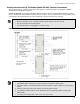
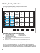
Common Controls
System Reset Button (White)
The System Reset button resets the fire alarm control panel and all circuits:
Signal Silence Button (Blue)
Pressing the Signal Silence button after the panel is in alarm turns on the Signal Silence LED and deactivates any
silenceable indicating circuits. Non-Silenceable circuits are unaffected. Signals will re-sound upon any subsequent
Alarm. This button does not function during any configured Signal Silence Inhibit timer period. It also does not
function if indicating circuits are active as the result of a Fire Drill. In a two stage system, if the Auto General Alarm
timer has timed out, the Signal Silence button also performs the same function as the Acknowledge button.
Fire Drill Button (Orange)
The Fire Drill button activates all programmed and non-disconnected indicating circuits, but does not transmit any
Alarms via the city tie or common alarm relay. The Fire Drill button may be programmed to operate specific
indicating circuits. The Fire Drill is cancelled by pressing the button again (toggle switch), or if the panel goes into a
real Alarm.
Acknowledge Button (Yellow)
If the Panel is not configured for two stage operation, this button does nothing. If the panel is configured for two
stage operation, pressing the Acknowledge button while the Auto General Alarm timer is timing (there is an Alarm in
•Resets all latching trouble conditions •Resets all initiating circuits
•Resets four-wire smoke supply •Turns off all indicating circuits
•Turns off Signal Silence,
Acknowledge & General Alarm
LEDs
•Turns off Fire Drill
•Stops and resets all timers •Processes inputs as new events
•Aux Disconnect is not affected
•Reset cannot be activated until the Signal Silence
Inhibit timer has expired