
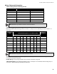
Specifications

Indicators, Controls, and Operation
32
Indicators, Controls, and Operation
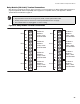
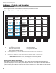
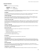
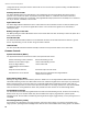
Refer to Figure 25 below for LED indicators, control buttons, and switches locations.
Figure 25 Indicators and Control Location
The main display panel on the fire alarm control unit consists of:
Paper labels for buttons and indicators
Each display is supplied with laser printable labels. These labels slide into the plastic label templates on the
panel.The label paper for the main display includes English and French versions (Mircom #NP-2854NP-680). Two
slide-in labels are also included for single-stage and two-stage operation. For the adder display, the labels are blank
(Mircom #NP-681).
A)
• 16 common LED indicators • 8 Common Buttons
• 28 circuit / circuit indicators • Configuration DIP switch
• 28 circuit disconnect DIP switches
B) An adder display module is part of the ECH-1048 Expander Chassis, which adds 48 circuit / circuit indicators
and disconnect switches.
C)
LED indicators may be amber, red, or green, and may illuminate continuously (steady), or at one of two flash
fates
• Fast flash: 120 flashes per minute, 50% duty cycle, for supervisory alarms
• Trouble flash: 20 flashes per minute, 50% duty cycle
1814 18 18 18
CONFIG.
SIG. ZONE
DISCONNECT
DET. ZONE
DISCONNECT
ZONE
DISCONNECT
ZONE
DISCONNECT
COMMON
1
ZONE
2
ZONE
3
ZONE
4
ZONE
5
ZONE
6
ZONE
7
ZONE
8
ALARM
SUPERVISORY
COMMON
REMOTE
FAILURE
TEST/CONFIG
MODE
SYSTEM
RESET
FIRE
DRILL
ACKNOW-
LEDGE
GENERAL
ALARM
COMMON
TROUBLE
A.C.
ON
LAMP
TEST
AUXILIARY
DISCONNECT
BUZZER
SILENCE
SIGNAL
SILENCE
CPU FAULT
GROUND FAULT
SIGNAL 1
TROUBLE
SIGNAL 2
TROUBLE
SIGNAL 3
TROUBLE
SIGNAL 4
TROUBLE
ZONE
BATTERY/
CHARGER
TROUBLE