
Specifications

Field Wiring
28
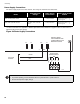
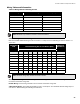
Power Supply Connections
The power supply is part of the main chassis. The ratings are outlined in the table below.
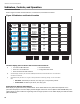
For more information see Appendix C: Module Specifications and Features on page 57. Wire as shown below in
Figure 24 using proper wire gauges.
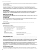
Figure 24 Power Supply Connections
Model
Electrical Input
Ratings
Power Supply
Total Current
Battery Fuse on Main
Module
MCC-1024-6(S) Main Chassis
120 VAC, 60 Hz / 240 VAC,
50Hz
6 amps maximum
Replace with 20 amp, 1
¼
"
Fast Acting Fuse
MCC-1024-12(S) Main Chassis
120 VAC, 60 Hz / 240 VAC,
50Hz
12 amps maximum
Replace with 20 amp, 1
¼
"
Fast Acting Fuse
ATTENTION:
• To prevent sparking, connect batteries after the system main A.C. power turns on.
• Do not exceed power supply ratings.
P9
CONNECT GREEN
EARTH GROUND WIRE
TO MAIN MODULE PCB
MOUNTING SCREW.
TO 24 VDC
BATTERY
BLACK
P7P8 P10
+
-
BAT
RED
LL
N
G
GREEN
TO DEDICATED
BRANCH CIRCUIT
240V, 50Hz
120V, 60Hz