
Specifications

FA-1000
Installation and Operation Manual
23
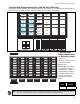
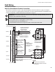
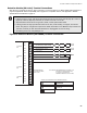
Detection Module (DM-1008A) Terminal Connections
Wire devices to terminals as shown in Figure 19 below. For more information see Wiring Tables and Information on
page 29, Appendix B: Device Compatibility List on page 50 for compatible devices, and Appendix C: Module
Specifications and Features on page 57.
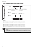
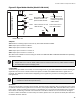
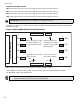
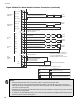
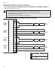
Figure 19 Detection Module (DM-1008A) Terminal Connections
Note:
• Initiating circuits in an FA-1000 Series Fire Alarm Panel must all be either Class B (Style B) or Class A
(Style D). If Class A (Style D) is selected, the number of circuits is cut in half.
• All power limited circuits must use type FPL, FPLR, or FPLP power limited cable.
• Initiating circuits are fully supervised and rated for 22 VDC, 3 mA standby, 5 mV ripple, 50 mA max
alarm. They may be configured as required. The alarm threshold is 21 mA. Maximum loop resistance is
100 ohms, 50 ohms per side.The terminal blocks are "depluggable" for ease of wiring.
• All initiating circuits are Compatibility ID "A".
SUPERVISORY OR
WATERFLOW
SWITCH (NO)
HEAT DETECTOR
LEGEND: (SEE APPENDIX B FOR COMPATIBLE DEVICES)
SMOKE DETECTOR
3.9K 1/2W ELR LISTED S5434
MODEL MP-300 MANUFACTURED
BY MIRCOM
INI1+
INI1-
INI2+
INI2-
INI3+
INI3-
INI4+
INI4-
STYLE B/D
INI2
STYLE B/D
INI1
PULL STATION
STYLE B
WIRING
STYLE D NOTE: INITIATING CIRCUITS IN A SERIES 1000
MUST BE ALL EITHER STYLE B OR D.
IF STYLE D IS SELECTED, THE
NUMBER OF CIRCUITS IS CUT IN HALF.
STYLE B
WIRING
STYLE D
WIRING
SUPERVISED INITIATING CIRCUIT #2
(SUPERVISORY OR WATERFLOW ZONE)
(POWER LIMITED)
SUPERVISED INITIATING CIRCUIT #1
(ALARM ZONE) (POWER LIMITED)
SUPERVISED INITIATING CIRCUIT #2
(ALARM ZONE) SEE STYLE D NOTE (POWER LIMITED)
INI5+
INI5-
INI6+
INI6-
INI7+
INI7-
INI8+
INI8-
STYLE B/D
INI4
STYLE B/D
INI3
INITIATING CIRCUITS
5 TO 8 ARE NOT AVAIL.
ON FA-1012K.