
Specifications

FA-1000
Installation and Operation Manual
19
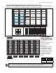
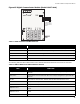
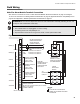
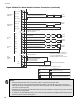
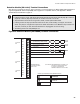
Figure 15 Digital Communicator Module (Model UDACT-300A)
Table 1 Cable Connectors and Miscellaneous
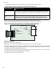
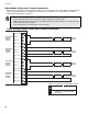
The following table lists all the LEDs located on the UDACT-300A board and states the function of each LED.
Table 2 UDACT-300A List of LEDs and their Functions
Cable Connector Function
P1 Ribbon Cable for connecting to Mircom Fire Alarm Control Panel (FACP)
P2 RS-232C/RS-485 Connection for computer configuration.
U18 Connector for CFG-300 Configuration Tool
Lamp Test button
Press and hold this button to test all the
UDACT-300A
LEDs and LCD display
UR1 Potentiometer This potentiometer is for adjustment of the CFG-300 LCD contrast.
LEDs FUNCTION
Relay Line 1
Located below Line 1 terminal block. When Line 1 relay is energized, this green LED will
illuminate
Relay Line 2
Located below Line 2 terminal block. When Line 2 relay is energized, this green LED will
illuminate.
RS-485 Status LED for communication, will flash when RS-485 communication is active.
Common Trouble
Steady amber for any troubles on the Fire Alarm panel or
UDACT-300A
.
CPU Fail Steady amber for any on board CPU trouble.
Telephone Line 1
Telephone status indicator LED; Red when the line is in use, Amber when there is a line
trouble.
Telephone Line 2
Telephone status indicator LED; Red when the line is in use, Amber when there is a line
trouble.
Power ON Green LED is ON steady when power is supplied to the board.
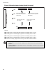
CONNECT RIBBON
CABLE FROM P1
TO MIRCOM FIRE
ALARM CONTROL
PANEL
VR1