
Specifications
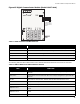

Module Settings
16
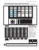
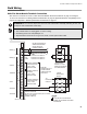
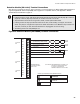
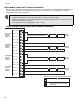
Figure 12 Detection Adder Module (Model DM-1008A)
Jumpers
JW1: Install jumper for Class A (Style D) operation of initiating circuits 1 and 2.
JW2: Install jumper for Class A (Style D) operation of initiating circuits 3 and 4.
JW3: Install jumper for Class A (Style D) operation of initiating circuits 5 and 6.
JW4: Install jumper for Class A (Style D) operation of initiating circuits 7 and 8.
JW5: Remove continuity jumper if there are any more adder modules installed.
Notes:
• Jumper JW6 on the main fire alarm module must be removed if there are any adder modules
installed.
•The
DM-1008A
requires eight display points for Class B (Style B) operation, and four for Class A
(Style D) operation.
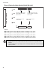
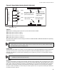
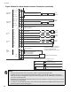
P1
P3
P4
FIELD WIRING TERMINALS
P2
JW5
JW4
JW3
JW2
JW1
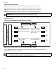
Data cable to P5 of main fire
alarm module or to previous
adder module.
Power connector to P6 of main
fire alarm module or to previous
adder module.
Data connector for next
adder module.
Power connector for next
adder module.