
Specifications

FA-1000
Installation and Operation Manual
13
Module Settings
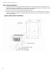
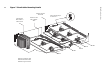
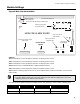
Figure 8 Main Fire Alarm Module
Jumpers
JW1: Install jumper for Class A (Style D) operation of initiating circuits 3 and 4.
JW2: Install jumper for Class A (Style D) operation of initiating circuits 5 and 6.
JW3: Install jumper for Class A (Style D) operation of initiating circuits 7 and 8.
JW4: Remove jumper if a PR-300 Module or UDACT-300A is installed.
JW5: Install jumper for Class A (Style D) operation of initiating circuits 1 and 2.
JW6: Remove continuity jumper if there are any circuit adder modules installed, and install it on the last circuit
adder module.
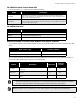
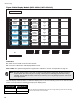
The main fire alarm module contains the following circuits, each requiring a certain number of display points:
Notes:
• The main display module (part of the main chassis) has four dedicated display points for the four
indicating circuits on the main fire alarm module.
Chassis Type Initiating Circuits Indicating circuits Display Points Required
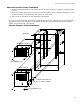
MCC-1024-6(S) 8 Style B / 4 Style D 4 Style Y or Z 8/4 (Style B / D)
MCC-1024-12(S) 8 Style B / 4 Style D 4 Style Y or Z 8/4 (Style B / D)
MAIN FIRE ALARM BOARD
FIELD WIRING TERMINALSP1
P4
P5
P6
F1
P8 P7 P10 P9
-BDG+ -B
A
T+
P3
JW1
P2
JW4
JW2 JW3
JW5
JW6
RS-485 connection
for future expansion
Connector for PR-300 Module or UDACT-300A
Connector for display module
(MCC-1024)
Connector for future
expansion
Factory connection to
Bridge Rectifier
Connection to
24VDC battery
Power connector for
adder modules
Connector for circuit adder
modules
Connector for future
expansion
Remove these jumpers
to program Class B