
Specifications
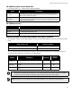

FA-1000
Installation and Operation Manual
11
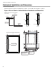
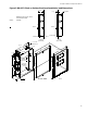
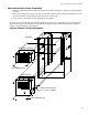
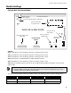
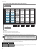
Figure 6 BB-1072 Expansion Chassis Mounting Locations
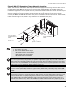
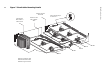
The BB-1072 enclosure with an ECH-1048 expander chassis is equipped with two long extension cables: one for
the 26-pin ribbon cable (MD-575) and one for the four-wire power cable (MD-580). Circuit adder modules are
installed from right to left in two tiers (back then front). These circuit adder modules are cabled in the same way as
the main chassis, except that the first module on the back tier to the right connects (via the MD-575 and MD-580
extension cables) to the second module in the main chassis. The fourth module on the front tier to the right
connects (via MD-575 and MD-580 extension cables) to the third module on the first tier to the left. In other words,
follow a continuous right to left, bottom to top, and back to front installation order (see ).
Notes:
1. Front plate is not shown.
2. Other circuit adder modules may be:
• DM-1008A Detection Circuit Module
• SGM-1004A Signal Circuit Module
• RM-1008A Relay Circuit Module
ATTENTION: There needs to be enough display points for each circuit on an adder module. These display
points are assigned during configuration (see System Configuration on page 40) in the order in which the
adder modules are electrically installed (the order in which they have their cables connected to each other).
Both the number of points available for each display type and the number of points required for each circuit
adder module type are described in Module Settings on page 13.
ATTENTION: As good practice, it is recommended that circuit adder modules are installed in the order of
detection modules (DM-1008A) followed by signal modules (SGM-1004A), followed by relay modules (RM-
1008A).
ATTENTION: To enable communication from the main fire alarm module to all of the circuit adder modules,
it is necessary to remove the continuity jumper on JW6 (near P5, the circuit adder module connector) on the
main fire alarm module. This jumper plug must be installed on the continuity jumper on the last installed
circuit adder module (see Module Settings on page 13 to verify the location of the continuity jumper on a
particular circuit adder module). Note: Only the last circuit adder module should have a jumper plug on its
continuity jumper - all others must be left without a jumper plug.
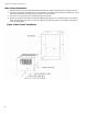
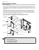
#6-32 X 1
1
/
4
”
screw
other circuit adder
module (see Note 2
below)
#6-32 1
1
/
2
” M/F hex
spacer
other circuit adder
modules (see Note 2
below)