
Specifications
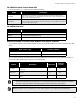

FA-1000
Installation and Operation Manual
9
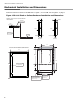
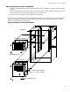
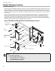
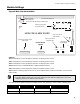
Main and Expander Chassis Installation
1. Install the main and expander chassis into the BB-1072 enclosure, as shown in Figure 4, using the supplied
hex-nuts.
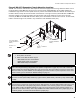
2. Group the incoming wires through the top of the enclosure to prepare them for wiring the modules. Do not run
the wires in-between the modules since this could cause a short circuit.
3. Use a wire tie to group wires for easy identification and neatness.
Be sure to connect a solid earth ground (from building system ground / to a cold water pipe) to the chassis earth
ground mounting lug, and to connect the earth ground wire lugs from both the main chassis and the expander
chassis to the ground screw on the backbox.
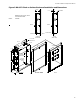
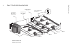
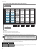
Figure 4 Expander Chassis Installation
MAIN CHASSIS
EARTH GROUND LUG
BACKBOX
#8-32 HEXNUTS (4X)
#8 x 1/4" TYPE `B' SCREW
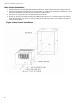
DISCONNECT
ZONECONFIG.
ALARM
1
SILENCE
CIRCUIT
BREAKER
A.C. LI NE
DET. ZONE
DISCONNECT
SIG. ZONE
DISCONNECT
8141
DISCONNECT
ZONE
8181
DISCONNECT
AUXILIARY
ACKNOW-
LEDGE
GENERAL
FIRE
DRILL
SILENCE
BUZZER
SIGNAL
TEST/CONFIG
FAILURE
RESET
SYSTEM
MODE
REMOTE
A.C. ON
LAMP
TEST
TROUBLE
COMMON
FAULT
SUPERVISORY
COMMON
BATTERY
TROUBLE
GROUND
COMMON
ALARM
8
EXPANDER CHASSIS
#8-32 HEXNUTS (4X)