Kaleido-K2 Guide to Installation and Operation High Resolution Virtual Monitor Wall Processor Copyright 2006 Miranda Technologies Inc. Specifications may be subject to change. Printed in Canada November 2006 Miranda Technologies inc. 3499 Douglas-B. Floreani St-Laurent, Québec, Canada H4S 1Y6 Tel. 514-333-1772 Fax. 514-333-9828 www.miranda.
GUIDE TO INSTALLATION AND OPERATION Safety Compliance Information Safety Compliance This equipment complies with: - CSA C22.2 No. 60950-1-03 / Safety of Information Technology Equipment, Including Electrical Business Equipment. UL 60950-1 (1st Edition) / Safety of Information Technology Equipment, Including Electrical Business Equipment. st IEC 60950-1 (1 Edition) / Safety of Information Technology Equipment, Including Electrical Business Equipment.
GUIDE TO INSTALLATION AND OPERATION Contents 1 Kaleido-K2 High Resolution Virtual Monitor Wall Processor .................................................................... 1 1.1 Introduction............................................................................................................................................... 1 1.2 Features ...................................................................................................................................................
GUIDE TO INSTALLATION AND OPERATION Kaleido K2
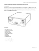
GUIDE TO INSTALLATION AND OPERATION 1 Kaleido-K2 Ultra High Resolution Virtual Monitor Wall Processor 1.1 Introduction The Kaleido-K2 Ultra High Resolution Virtual Monitor Wall Processor is designed as the ultimate solution to signal monitoring requirements. It accepts inputs in many standard formats; each input is equipped with its own advanced de-interlacing and scaling engine for highest display quality.
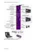
GUIDE TO INSTALLATION AND OPERATION REF Input Figure 1.2.
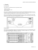
GUIDE TO INSTALLATION AND OPERATION 2 Overview 2.1 Front Panel The front panel of the Kaleido-K2 has three operational elements: - ON/OFF pushbutton - System status indicator LED - CPU reset button. These items are actually located on the front edge of the controller card. The LED and reset button are accessed through holes in the panel; the power button on the panel pushes against a smaller button located on the card.
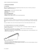
GUIDE TO INSTALLATION AND OPERATION 3 Mechanical Installation 3.1 Unpacking Make sure the following items have been shipped with your Kaleido. If any of these are missing, contact your distributor or Miranda Technologies Inc.
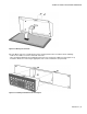
GUIDE TO INSTALLATION AND OPERATION Figure 3.2.2 Moving the connector Once the DE-9 connector is installed in the proper opening and the unit reassembled, do the following: - Remove the 4 rubber feet on the underside of the unit. - Place the Kaleido-RCP into the mounting bracket and secure it using the supplied screws (figure 3.2.3). - Install the unit into the rack using the appropriate rack screws and washers (not provided). Figure 3.2.
GUIDE TO INSTALLATION AND OPERATION 4 Frame and Electrical Installation Kaleido is a self-contained unit consisting of a frame, redundant power supplies, a controller card, and various input and output cards. 4.1 Frame The frame is 4 RU high. It incorporates an internal midplane for interconnecting the modules. Modules are installed from the front of the frame. Each module is associated with input and/or output connectors which are mounted on a connector panel.
GUIDE TO INSTALLATION AND OPERATION 4.2.2 Operation Connect each power supply to a power source using the supplied power cords. In normal operation, both supplies should be switched ON (power switch on the power supply unit set to | ). A green status lamp will illuminate on the power supply unit (see figure 4.2.1.1). 4.2.3 Ventilation Each power supply has its own integral ventilation fan.
GUIDE TO INSTALLATION AND OPERATION 4.3.1 Connector panel installation Remove the blank panel (a blank panel is used to occupy the rear panel space behind empty slots) or existing connector panel. Release the captive screws at the top and bottom, and pull the panel straight out of the frame. Slide the new connector panel into the slot on the rear of the frame. Push it gently into position until the panel is tight against the frame and flush with the remaining panels.
GUIDE TO INSTALLATION AND OPERATION The location of the connectors differs between input and output cards, so placing the wrong type of card in a slot is simply not possible. The two output cards provide identical outputs. 4.4 Module description and connection Each Kaleido must be equipped with a Controller module and an output card, and may be equipped with a variety of audio and video input modules depending upon the operational environment.
GUIDE TO INSTALLATION AND OPERATION The rear connector panel (11) associated with the Controller module has the following connectors: Ethernet: RJ-45 connector Ethernet interface for connection to LAN/WAN networks using TCP-IP. RS-422/485: DE-9S connector For connecting the Kaleido-RCP or other remote control devices. Figure 4.4.1.2 RS-422/485 Connector pin-out RS-232 : DE-9P connector To connect to router status information sources for tracking UMDs. Figure 4.4.1.
GUIDE TO INSTALLATION AND OPERATION Green indicates that the unit is properly powered and that one or both power supplies are on. Red indicates a stand-by mode: the unit is plugged in but the Controller is not switched on. CPU Reset switch: If the Controller is not working properly, it can be reset using this switch without the need to remove the front panel. Use a paper clip through the hole to depress the reset switch.
GUIDE TO INSTALLATION AND OPERATION 4.4.2 GPI Module The GPI module provides interfaces and processing to support 66 contact closure tally inputs and 36 contact closure alarm outputs. Four DC-37S connectors are installed on the MWR-GPI rear connector panel (10). The connector pinout and circuit schematics are shown in figure 4.4.2.2 and 4.4.2.3 respectively. Figure 4.4.2.1 GPI rear connector panel Figure 4.4.2.
GUIDE TO INSTALLATION AND OPERATION GPI inputs characteristics: Signal: 64 short-to-ground inputs Connector: DC-37S GPI outputs characteristics: Signal: 66 opto-isolated contact closures Connector: DC-37S Characteristics: Max differential voltage: 12 VDC Max sink current: 70 mA Isolation voltage: 2500 VRMS Figure 4.4.2.3 GPI connector pin-out To facilitate cabling of the GPI inputs and outputs, a terminal block adapter is available separately (Miranda P/N 1377-9800-100).
GUIDE TO INSTALLATION AND OPERATION 4.4.3 Analog Audio Input Module (MWI-SA) This module provides inputs for 16 channels of analog stereo audio. Two DSUB 50 connectors are available on the MWR-SA rear connection panel (8). Figure 4.4.3.1 MWI-SA rear connector panel Connect balanced analog stereo audio signals to the audio input connectors. Each connector receives 8 stereo inputs (refer to figure 4.4.3.2 below for connector pinout).
GUIDE TO INSTALLATION AND OPERATION 4.4.4 Digital Audio Input Module (MWI-AES) This module provides inputs for 16 channels of AES/EBU digital audio. A single DSUB 50 connector is available on the MWR-AES rear connection panel (9). Figure 4.4.4.1 MWI-AES rear connector panel Connect AES balanced audio signals to the audio input connector. Signal must conform to AES3-1992/ANSI S4.40-1992 standard. The DSUB 50 connector receives 16 inputs (refer to figure 4.4.4.2 below for connector pinout).
GUIDE TO INSTALLATION AND OPERATION Figure 4.4.5.1 MWI-CVBS rear connector panel 4.4.6 Y/C Analog Video Input Module (MWI-YC) This module provides inputs for 4 channels of Y/C (S-video) analog video. The inputs are mini-DIN 4-pin connectors, internally terminated and available on the MWR-YC rear connection module (5). The MWR-YC accepts NTSC or PAL, PAL-M, PAL-N Y/C signals conforming to the SMPTE 170M or ITU-R BT.470-6 standard respectively. Figure 4.4.6.
GUIDE TO INSTALLATION AND OPERATION Figure 4.4.7.3 MWA-BOC cable adapter 4.4.8 Digital Video SD-SDI Input Module (MWI-SDI) This module provides inputs for four channels of serial digital video. The inputs are on BNC connectors and are available on the MWR-4B rear connection module (2). The MWI-SDI accepts a 4:2:2 serial digital video signal in either 525 or 625-line format. This input must conform to the SMPTE 259M-C standard.
GUIDE TO INSTALLATION AND OPERATION Figure 4.4.8.2 DE-15P connector pinout 4.4.10 HD-SDI Video Input Module (MWI-HD) This module provides three standard- and high-definition digital video inputs. The HD/SDI video input module accepts 4:2:2 standard definition serial digital video signal in either 525 or 625-line format, conform to the SMPTE 259M-C standard and high-definition serial digital video signal conform to the SMPTE-292M-1998 standard.
GUIDE TO INSTALLATION AND OPERATION Figure 4.4.11.2 Audio monitoring connector pinout MON OUT: Provision for Monitoring output in SDI or Composite. Two slots are provided in the frame for the installation of output modules, increasing the flexibility of output management. During the boot up process and when the application is not running, the Graphic Background is normally disabled. A switch on the Output Module MWO-HR allows the Background signal out of the Graphic card to be displayed directly.
GUIDE TO INSTALLATION AND OPERATION Figure 4.5.1 Cascading two Kaleido-K2s Figure 4.5.1.
GUIDE TO INSTALLATION AND OPERATION 4.5.2 Controlling multiple Kaleido-K2s using RS-422 with a Kaleido-RCP Using the RS-422 communication port also allows up to 99 daisy-chained Kaleido-K2 frames to be controlled using only one Kaleido-RCP. With a multi-drop cable, this port directs communication between a series of Kaleido-K2 frames and the Kaleido-RCP. Figure 4.5.1.2 illustrates cabling between the Kaleido-K2s and Kaleido-RCP.
GUIDE TO INSTALLATION AND OPERATION 5 Operation The function of Kaleido-K2 is to gather information from multiple sources and merge it into a single information stream for presentation on a monitor. This process is managed under software control. The Kaleido software package consists of two parts: - Kaleido software runs on the on-board computer under Windows 2000, and manages the source processing and integration. It interfaces with remote controllers for real-time modification of the presentation.
GUIDE TO INSTALLATION AND OPERATION 6 Maintenance 6.1 Cleaning the air filter Occasionally, the air filter has to be removed and properly cleaned in order to maintain proper ventilation. To remove and clean the air filter, follow these directions: 1. Remove the front panel door by first removing the locking screws using a philips screwdriver and rotating the quarter-turn latch toward the center of the front panel. 2. Remove the air filter located at the bottom of the front panel. 3.
GUIDE TO INSTALLATION AND OPERATION 5. Remove the 4 screws that hold the fan onto the bracket, then remove the fan. 6. Install the new fan using the 4 retaining screws. 7. Plug in the fan power connector. Reinstall the fan bracket and the connector panels. 8. Turn on the unit. Figure 6.3.
GUIDE TO INSTALLATION AND OPERATION 7 Specifications INPUT COMPOSITE VIDEO INPUT (MWI-CVBS) SIGNAL (4): NTSC (SMPTE 170M), PAL, PAL-M, PAL-NITU 624-4, SECAM RETURN LOSS: > 35 dB up to 5.75 MHz QUANTIZATION: 8 bits CONNECTOR: BNC Y/C VIDEO INPUT (MWI-YC) SIGNAL (4): RETURN LOSS: QUANTIZATION: CONNECTOR: NTSC (SMPTE 170M), PAL, PAL-M, PAL-NITU 624-4 > 35 dB up to 5.75 MHz 8 bits Mini-Din 4 pins COMPONENT VIDEO INPUT (MWI-CAV) SIGNAL (4): Y, B-Y, R-Y 0.
GUIDE TO INSTALLATION AND OPERATION SCALES: EBU DIGITAL PPM (IEC-60268-18), NORDIC (IEC-60268-10 TYPE I), BBC/UK PPM(IEC-60268-10 TYPE IIA), EBU PPM (IEC-60268-10 TYPE IIB) PROGRESSIVE RGBHV INPUT (MWI-VGA) SIGNAL (2): Analog RGBHV RESOLUTION: From 640 x 480 to 1600 x 1200 NI signals REFRESH RATE: Up to 85 Hz RETURN LOSS: > 15 dB up to 65 MHz LEVEL: 0.4 to 1.
GUIDE TO INSTALLATION AND OPERATION OUTPUT PROGRESSIVE RGBHV OUTPUT 1 (MWO-HR) SIGNAL: Analog RGBHV RESOLUTION: From 800 x 600 to 1600 X 1200 NI H FREQUENCY: 31 kHz to 96 kHz REFRESH RATE: 50/59.94 Hz CABLE LENGH: 5m (low), 20m (medium) and 50m (high) cables built-in equalizer (Belden 1694) LEVEL: Selectable 0.7 or 1.0 Vp-p CONNECTOR: DE-15S (female) PROGRESSIVE RGBHV OUTPUT 2 (MWO-HR) SIGNAL: Analog RGBHV RESOLUTION: From 800 x 600 to 1600 X 1200 NI H FREQUENCY: 31 kHz to 96 kHz REFRESH RATE: 50/59.
GUIDE TO INSTALLATION AND OPERATION REMOTE PORT (MWA-CPU) DESCRIPTION: SIGNAL: CONNECTOR: Remote control panel communication port RS-422 (SMPTE 207M, EBU-3245), RS-485 with 12V supply on pin 5 DE-9S (female) ETHERNET PORT(MWA-CPU) SIGNAL: 10/100 BASE-T (IEEE 802.3) CONNECTOR: RJ-45 USB PORT(MWA-CPU) SIGNAL: CONNECTOR(2): USB Ver 1.0 USB PS/2 PORT(MWA-CPU) SIGNAL (2): CONNECTOR: Keyboard/mouse PS/2 FRAME POWER SUPPLY: INPUT VOLTAGE: FREQUENCY: POWER: DIMENSION: WEIGHT: FULL SPEC. TEMP.