
User guide


13
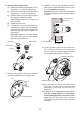
12. Insert the wall plugs (supplied) and attach
the mixer to the wall or timber noggin with the
screws provided.
13. Fit the compression nuts and olives onto the
pipework, connect the pipes and tighten the
compression nuts.
Important! Make sure that the outlet pipework
protrudes through the wall by approximately
30 mm and temporarily cap off.
Important! For stud partition/laminated panel
installations t the wallplate over the outlet
pipework on the inside of the panel. The outlet
pipework should then be installed through a
25 mm hole in the panel.
Screws
Outlet Pipe to Fittings
Hot Supply
Cold Supply
14. Turn on the water supplies and check for
leaks.
15. Determine the nished wall position (e.g. tile
thickness). Turn off the water supply, carefully
uncap the outlet pipe and cut to length, the
outlet pipe must protrude through the nished
wall surface by 21–23 mm.
Note! Remove any burrs from the pipes before
proceeding.
16. For solid wall installations go to instruction
17.
For stud partition/laminated panel installations,
nish the wall, then go to instruction 25.
Important! Make sure that you use the
cardboard building-in shroud when nishing
the wall. This will protect the valve and make
sure that you tile up to the correct diameter.
Caution! Make sure that the nished wall is
within the maximum and minimum limits and to
an even depth (no greater than 2 mm variation)
or the controls will not t correctly.
Cardboard
Building-in Shroud
17. Loosely screw the RAC backplate to the
wallplate, using the two backplate screws
provided.
18. Place the backplate/wallplate assembly over
the outlet pipe with the arrow pointing vertically
up. The screw holes should be at 40° to the
horizontal.
19. Mark the positions of the two wallplate xing
holes.
Wallplate
RAC Backplate
Backplate Screws
Arrow
40°