CPE ON-LINE SERIES User’s Manual Para Systems, Inc. 1455 LeMay Dr. Carrollton, TX 75007 Phone: 1-972-446-7363 Fax: 1-972-446-9011 Internet: minutemanups.com UPS Sizing: sizemyups.
Table of Contents Important Safety Instructions .................................................................2 1. Introduction ..........................................................................................5 1.1. The General Characteristics ...........................................................6 1.2. The Advanced Technical Characteristics........................................6 2. Introduction to the Front and Rear Panel..........................................7 2.1.
IMPORTANT SAFETY INSTRUCTIONS This manual contains important instructions that should be followed during the installation and the maintenance of the UPS. • • • • SAVE THESE INSTRUCTIONS • An Important Notice • • • • • • • • • • • • • • • • • • • To ensure safety in all applications where a UPS is hardwired to the Electrical Supply, ensure that a Qualified Service Personnel installs the system. Those UPS systems supplied with a power cord can be safely connected to the wall outlet by the user.
• • NOTICE: – This equipment has been tested and found to comply with the limits for a Class A computing device in accordance with the specifications in Subpart J of Part 15 of FCC Rules and the Class A limits for radio noise emissions from digital apparatus set out in the Radio Interference of the Canadian Department of Communications. These limits are designed to provide reasonable protection against such interference in a residential installation.
1.1. The General Characteristics • • • • • • True On-Line architecture continuously supplies your critical device with a stable, regulated, transient-free, pure sine wave AC Power. 50KHz PWM sine wave topology yields an excellent overall performance. The high crest factor of the inverter handles all high-inrush current loads without a need to upgrade the power rating. To protect the unit from overloading, it automatically switches to Bypass mode in case loading exceeds 120% of rating.
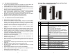
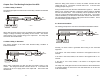
2.2. Rear Panel Explanation 2.2.1 General Explanation a) 120VAC 1. 6 6 8 8 2. 5 5 6 8 4 2 5 7 1 3 7 4 4 7 3 3 External Battery Connector 4. This is used to connect the protected equipment. Output Receptacles Receptacle 1K 2K 3K type 120V Models NEMA 4pcs 4pcs 6pcs 5-15R NEMA N/A 2pcs 2pcs 5-15/20R 230V Models Receptacle 1K 2K 3K type IEC 3pcs 3pcs N/A Schuko 1pce 2pcs 2pcs Sockets Terminal N/A N/A Yes Block Option Slot It is used for the Option Cards.
2.2.2 Terminal Block Explanation For 3K Tower Type 230V Only 2.3.3. The Pin Assignments of PP Contact Card Pin 1: UPS Shutdown, RS232 Input (+3.3 ~ +25VDC/5-seconds) Pin 2: Line Fail Signal RS232 Output (Low to High) Pin 3: Line Fail Signal Normally Open (40VDC/25mA) Pin 4: Common Pin 5: Low Battery Signal Normally Open (40VDC/25mA) Pin 6: Line Fail Signal Normally Closed (40VDC/25mA) Pin 7: Reserved Pin 8: Reserved Pin 9: Common Chapter Three: Installation and Operation 2.
1. Keep at least 20cm (8-inches) clearance from the rear panel of the UPS to the wall. 2. Do not block the airflow to the ventilation openings of the unit. 3. These UPSs are intended for a Controlled Environment. 4. Do not place the UPS in an environment near dusty, corrosive or flammable materials. 3.3. Connecting the Batteries Be sure to read all of the WARNINGS and the CAUTIONS before installing the UPS.
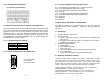
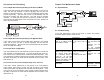
When the Utility power returns to normal, the AC/DC converter and the charger will turn on. The DC/DC converter will turn off. It has the same working principle as figure 4.1. Chapter Four: The Working Principle of the UPS 4.1. When Utility is Normal The working principle of the UPS under normal Utility conditions is illustrated as follows: RECTIFIER O/P OUTPUT During a blackout, the UPS will work as illustrated in figure 4.2.
4.4. Inverter not Functioning Chapter Five: Maintenance Guide 4.4.1. Output Short-Circuit operating in the On-Line Mode 5.1. System Block If the output load becomes short-circuited while operating in the On-Line mode, the UPS will shutdown to prevent damaging the UPS and the remaining connected equipment. The Fault LED illuminates and the alarm sounds continuously. The UPS will not turn on automatically after the short-circuit condition has been removed. The UPS must be manually restarted.
Situation Check Items The Battery Low LED is illuminated. Solution The UPS is on battery power and the battery is almost exhausted. The UPS will shutdown shortly. When the Utility power returns recharge the battery. The Fault LED is Disconnect the connected illuminated. equipment. Turn the UPS off and then back on again. If the Fault LED is still on call for Service. If the Fault LED is not on, your equipment probably has a short-circuit.
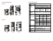
• CAUTION – Replace batteries with the same number and type as originally installed in the UPS. These batteries have pressure-operated vents. These UPSs contain sealed non-spillable lead acid batteries. Model Number CPE 1000 CPE 2000 CPE 3000 CPE 1000i CPE 2000j CPE 3000i CPE 2000i Battery 3-12V7.2Ah 6-12V7.2Ah 8-12V7.2Ah QTY/Rating CSB GP1272 F2 GP1272 F2 GP1272 F2 Part Number Panasonic LC-R127R2CH1 LC-R127R2CH1 LC-R127R2CH1 Part Number Yuasa NPW36-12 NPW36-12 NPW36-12 Part Number 5.5.
CPE 2000, CPE 2000j, CPE 2000i CPE 3000, CPE 3000i 1 2 3 4 22 23
Chapter Six: Power Monitoring Software Installation Guide C. RUPS II for Novell Netware 6.1. Hardware Installation 1. Login the File Server as a SUPERVISOR or a USER with access rights in sub-directory SYS: SYSTEM. F:\>LOGIN SUPERVISOR 2. Insert the software CD into the CD drive and execute INSTALL.EXE. F:\>A: A:\>INSTALL 3. After the installation is complete, please shutdown your NetWare Operating System and restart it. The system will load the PowerMan.NLM and execute it. 4.
E. UPSilon 2000 for FreeBSD and Linux 1. Log in as a super-user. 2. Use the 'ftp' utility in MS-DOS to copy files into the system directory '/tmp'. 3. Follow the instructions below to make the filename conversion after the 'ftp' File transfer: #cd/tmp #mv linux.z linux.Z, or #mv LINUX.Z linux.Z #chmod 755 install 4. Execute the installation program: #./install. 5. Select a target system from the menu, and configure the UPSilon for Unix.
MODEL CPE 1000 CPE 1000i CPE 2000, CPE 2000j CPE 2000i CPE 3000 CPE 3000i If the UPS requires Service: PROTECTION Overload 100%~120% delay 60-seconds before switching to Bypass Mode. 120%~150% delay 10-seconds before switching to Bypass Mode. >150% immediately switches to Bypass Mode. Short-Circuit a) Inverter Mode: UPS shuts down. b) Bypass Mode: AC Input fuse opens. Overheat a) Utility Normal: Switch to Bypass Mode.
A.3. Limited Product Warranty A.4. Declaration of Conformity Para Systems Inc. (Para Systems) warrants this equipment, when properly applied and operated within specified conditions, against faulty materials or workmanship for a period of three years from the date of purchase. For equipment sites within the United States and Canada, this warranty covers repair or replacement of defective equipment at the discretion of Para Systems. Repair will be from the nearest authorized service center.