
Technical data

APPENDIX
CV ELECTRICAL POWER SYSTEM MAINTENANCE MANUAL 2A5A2-ELEC-MM-1-0 47
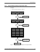
6.3 Electrical Cables Testing
CAUTION!
If salt water remains on a connector when it is inserted, the salt crystals could
potentially ruin the rubber connector seal. Thoroughly clean the contact points
with alcohol before connecting.
Special Tools
500 VDC insulation resistance meter
Calibrated thermometer
Procedure
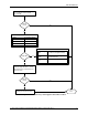
Verify Continuity
1. Using a Digital MultiMeter (DMM) and the cable schematic, verify the cable
continuity. Verify that the resistance of each conductor is less than 1 ohm. Most
DMMs have a continuity test that will beep when the probes are connected
across 1 ohm or less.
2. If any conductor has an end to end resistance greater than 1 ohm, replace the
cable as soon as possible.
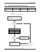
Measure Insulation Resistance
3. Measure and record ambient temperature.
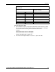
4. For all conductor to conductor combinations and all conductor to connector shell
combinations, using an insulation tester at 500 VDC, measure the resistance
between the test conductor and the remaining conductors connected together in
a group. That is, when testing a 25-pin cable, for the first test measure the
resistance between pin 1 and pins 2 through 25 connected as a group. For the
second test, measure the resistance between pin 2 and pins 3 through 25
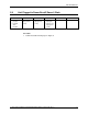
connected as a group. The sequence is shown in the table below:
Pin Pin
Shell 1-25
1 2–25
2 3–25
3 4–25
4 5–25
5 6–25
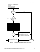
5. Record the measured insulation resistance twice, once at 30 seconds, and once
at 60 seconds.
6. If any measurement is less than value shown in table below, measure the
resistance between all combinations of single conductor to single conductor to
check for a failure.
7. If any single conductor to single conductor resistance test is less than value
shown in table below, record the result and replace the cable as soon as
possible.