
Technical data

CORRECTIVE MAINTENANCE
CV ELECTRICAL POWER SYSTEM MAINTENANCE MANUAL 2A5A2-ELEC-MM-1-0 27
Preconditions
None
Procedure
1. Follow instructions in Section 6.2, General Notes, regarding hazmat
requirements, torque specifications, inspection of mounting hardware, and use of
Nylok® nuts, as applicable.
2. Perform the following steps in accordance with local requirements for SOC and
tag in/out, as applicable.
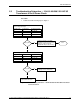
3. At the 208/120 VAC 3 ∅ distribution panel,
BUS #2, turn off breaker CB 10, POWER
ROOM OUTLET , POWER ROOM LIGHT,
and EMERGENCY LIGHTS.
4. Remove the light bulb cover in the defective assembly.
5. Remove both fluorescent light bulbs.
6. Open the ballast cover.
7. Disconnect the power wires to the ballast.
8. Remove the ballast.
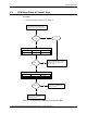
9. Install the new ballast.
10. Reconnect the power wires to the ballast.
11. Close the ballast cover.
12. Install new fluorescent light bulbs as required.
13. Reinstall the light bulb cover.
14. At the 208/120 VAC 3∅ distribution panel,
BUS #2, turn on breaker CB 10, POWER
ROOM OUTLET , POWER ROOM LIGHT,
and EMERGENCY LIGHTS. Confirm functionality
of the fluorescent light assembly.
15. Return valves and electrical switches to the state that they were in before this
procedure was performed.
16. Inspect and determine disposition of any parts removed. If applicable, dispose of
removed parts and/or fluids in accordance with local requirements.
17. Ensure the preceding steps were performed in accordance with local
requirements for SOC and tag in/out, as applicable.
0.