
Technical data


CORRECTIVE MAINTENANCE
CV ELECTRICAL POWER SYSTEM MAINTENANCE MANUAL 2A5A2-ELEC-MM-1-0 24
4.11 Replacing a Power Tray Power Supply
WARNING!
Shock hazard! Verify power to the unit is isolated before performing this
corrective maintenance procedure.
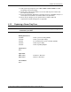
Drawing References
7533009 Power system assembly (2A5A2)
7533010 Power system cable routing
7533011 CV electrical power system schematic (2A5A2)
7533014 Power tray assembly
7533015 Power tray wiring diagram
7533118 Power tray installation details
Special Tools
None
Spare Parts
HAA15-0.8A Power supply, Power-One®
HAA5-1.5/OVP-A Power supply, Power-One®
HC12-3.4A Power supply, Power-One®
Preconditions
None
Procedure
1. Follow instructions in Section 6.2, General Notes, regarding hazmat
requirements, torque specifications, inspection of mounting hardware, and use of
Nylok® nuts, as applicable.
2. Perform the following steps in accordance with local requirements for SOC and
tag in/out, as applicable.
3. At the power tray front panel, turn off
BUS 1 POWER and BUS 2 POWER.
4. Remove four (4) bolts securing power tray to the control/power console and
gently pull out power tray. Ensure cables at the back of the tray are protected.
5. Disconnect wires at the power supply.
6. Remove screws securing the power supply.
7. Remove the power supply.
8. Install new power supply.
9. Reconnect wires to the power supply.
10. Gently push in power tray and reinstall four (4) bolts securing power tray to the
control/power console. Ensure cables at the back of the tray are protected.