
Technical data


CORRECTIVE MAINTENANCE
CV ELECTRICAL POWER SYSTEM MAINTENANCE MANUAL 2A5A2-ELEC-MM-1-0 17
9. Remove the transformer.
10. Install the new transformer.
11. Reinstall the transformer sensor panel support straps.
12. Reconnect ground wire.
13. At the input transformer tap, reconnect the input power wires at each of three (3)
taps
480. Reconnect two (2) voltage condition wires at ØA at tap 0 and 480.
14. At the output transformer terminal beam, reconnect three (3) PRM HPU power
wires at tap
3100.
15. Perform high voltage test (see Section 4.4, Measuring High Voltage).
16. If voltage reading is not acceptable, repeat Steps 12 through 14. Ensure wires
are reconnected properly and the input voltage at the transformer is 480 VAC, 3
Ø.
17. Restore power and confirm functionality of the system with the PRM attached.
18. Return valves and electrical switches to the state that they were in before this
procedure was performed.
19. Inspect and determine disposition of any parts removed. If applicable, dispose of
removed parts and/or fluids in accordance with local requirements.
20. Ensure the preceding steps were performed in accordance with local
requirements for SOC and tag in/out, as applicable.
0.
4.6 Replacing a Hotel Boost Transformer
DANGER!
Shock hazard! Verify power to the unit is isolated before performing this
maintenance procedure. This procedure exposes conductors that carry
high voltage sufficient to cause lethal electric shock.
When performing work in the CV power room, be aware of potential
exposure to high voltages sufficient to cause lethal electric shock.
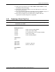
Drawing References
7533008 CV power system wiring diagram
7533009 Power system assembly (2A5A2)
7533010 Power system cable routing
7533011 CV electrical power system schematic (2A5A2)
7533016 Hotel and HPU transformer wiring diagram
7533307 Hotel boost transformer installation details
7533334 Hotel boost transformer sensor and terminal assembly
7533342 Hotel boost transformer assembly
Special Tools
None