
Technical data

PREVENTIVE MAINTENANCE
CV ELECTRICAL POWER SYSTEM MAINTENANCE MANUAL 2A5A2-ELEC-MM-1-0 8
9. Return valves and electrical switches to the state that they were in before this
procedure was performed.
10. Inspect and determine disposition of any parts removed. If applicable, dispose of
removed parts and/or fluids in accordance with local requirements.
11. Ensure the preceding steps were performed in accordance with local
requirements for SOC and tag in/out, as applicable.
0.
3.4 Replacing the PRM Hotel Power UPS Battery Pack
DANGER!
Shock hazard! Verify power to the unit is isolated before performing this
maintenance procedure. This procedure exposes conductors that carry
high voltage sufficient to cause lethal electric shock.
When performing work in the CV power room, be aware of potential
exposure to high voltages sufficient to cause lethal electric shock.
CAUTION!
Avoid touching battery terminals with objects that could create a short circuit.
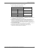
Drawing References
7533009 Power system assembly (2A5A2)
7533010 Power system cable routing
Special Tools
None
Spare Parts
569-COTS-ISE-0088 5000 VA on-line UPS model MCP 6001
See COTS sheet for replacement battery ordering information.
Preconditions
None
Procedure
1. Follow instructions in Section 6.2, General Notes, regarding hazmat
requirements, torque specifications, inspection of mounting hardware, and use of
Nylok® nuts, as applicable.
2. Perform the following steps in accordance with local requirements for SOC and
tag in/out, as applicable.
3. In the CV, at the
POWER DISTRIBUTION UNIT, set POWER BUS 1 (2A5A2-1B-EP01-1)
and
POWER BUS 2 (2A5A2-CB-EP01-2) to OFF.
4. At the
480 V 3Ø DISTRIBUTION PANEL, turn off BUS #1 MAIN DISCONNECT (2A5A2-CB-
EPO8-1) and
BUS #2 MAIN DISCONNECT (2A5A2-CB-EPO8-2) switches.